
Programming instructions

54
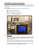
There are 4 different types of modules available.
• Analog I/O Modules (maximum 4 per CPU)
• High Speed Pulse Input Module (maximum 2 per CPU)
• High Speed Pulse Output Module (maximum 2 per CPU)
• Serial Communications Module (maximum 2 per CPU or 1 with a BD
board)
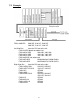
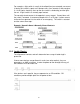
Analog Modules
The data is directly input into PLC memory addresses. The modules are
numbered out from the CPU to the left.
• 1
st
uses M8260-M8269 and D8260-D8269
• 2
nd
uses M8270-M8279 and D8270-D8279
• 3
rd
uses M8280-M8289 and D8280-D8289
• 4
th
uses M8290-M8299 and D8290-D8299
High Speed Pulse Input Modules
High speed pulse input modules are numbered from the CPU out to the
left.
• 1
st
unit uses X0, X1, X2, X6
• 2
nd
unit uses X3, X4, X5, X7
• High speed counters C235-C255 are used
Note that these are the same addresses used by the first 8 inputs on the
PLC. Only the 4HSX module OR the built-in I/O should be used. Do NOT
wire both.
High Speed Pulse Output Modules
High speed pulse input modules are numbered from the CPU out to the
left.
• 1
st
unit uses Y0, Y1, Y4, Y5
• 2
nd
unit uses Y2, Y3, Y6, Y7
Note that these are the same addresses used by the first 8 outputs on the
PLC. Only the 2HSY module OR the built-in I/O should be used. Do NOT
wire both.
Serial Communications Modules
Serial communication modules do not have input or output addresses.
Programming information for these modules is covered in the FX
Communications Manual, part number JY997D16901.