
Programming instructions


53
LESSON 7 - Addressing
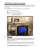
Controlling and monitoring I/O in a PLC program requires knowledge of the address of
the point to be controlled. The same applies to Special Function Modules. This chapter
explains how the addresses of the modules and I/O point in a system are determine
Lesson Objectives: At the conclusion of this lesson, you will be able to…
9 Correctly address a discrete input or output point.
9 Determine the address of a Special Function Module.
9 Describe the I/O limitations of an FX3U system
Materials: FX-Series PLC Training Manual
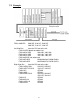
7.1 Right Side Bus Rules of Addressing
1) Addressing of inputs and outputs is in Octal (X0-X7, X10-X17, etc.)
2) Addressing for both inputs and outputs start at 0 (X0 and Y0)
3) Addressing is consecutive
4) SFMs are addressed as Blocks 0 – 7. The first SFM encountered to the right
of the processor is block 0; the next one is block 1, etc.
5) A maximum of 8 SFMs can be connected to a main unit
6) SFMs do not affect the addressing of I/O modules, and vice versa.
7) FX3U PLC cannot have more than 128 inputs and 128 outputs directly
connected. It is possible to extend to 384 I/O via network modules.
8) SFMs use 8 points of I/O each. This is deducted off the 256 I/O max. Thus
an FX3U with one SFM has a maximum I/O capability of 248 I/O. The
Maximum number of inputs possible is still 128, and the maximum number of
outputs is still 128, as long as 248 combined I/O is not exceeded.
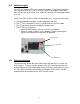
7.2 FX3U Left Side Adapter Bus Rules of Addressing
The FX3U series adds a new adapter bus on the left side of the PLC. This bus
has certain special adapter modules (ADP modules) which can be used to add
functionality to the PLC.