
Programming instructions


52
V and Z – Index Registers
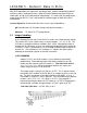
Index registers are indicated by the symbols V and Z. V and Z can both
be used for 16 bit applications, while only Z can be used with 32 bit
instructions. Values stored in an index register are used as offsets to
specified devices. There are 8 available V indexes (V0-V7) and 8
available Z indexes (Z0-Z7). Indexes are used by attaching their address
as a suffix to an address in the program. If V or Z are referenced without
a number, the number 0 is implied.
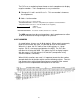
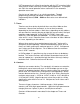
If V0 has the value of K2, then D10V is D10 + 2 = D12.
If Z2 has a value of K8, then Y1Z2 = Y11. Remember X and Y address in
octal, so the offset number is converted to octal and added to the base
address. Because 8 in decimal is 10 in octal, the address in increased by
10.
These devices are useful for accessing a large amount of information
without the use of a large number of rungs.
P - Pointers
P addresses are pointers. Pointers are used with jump, call, and interrupt
instructions to alter program flow. Call and JMP instructions cause the
program scan to stop in one area and to move to another, either by calling
a subroutine or by moving to another location in the same program. The
pointer is used as 1) the destination of a jump or call instruction and 2) as
the name of a jump point or subroutine.
K, H, and E – Numerical Constants
K, H and E are used to indicate a numeric constant. A PLC instruction will
not recognize a “1” written in Relay Ladder code, but would understand
“K1” or “H1”. A “K” indicates the constant is a decimal constant. The “H”
designates a hexadecimal constant. An “E” indicates a floating point
numeric value. Constants can be either 16 bit (-32768 to 32767) or 32 bits
(-2,147,483,648 to 2,147,483,647) in decimal.
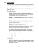
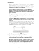
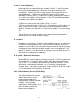
U\G – Buffer Memory Access (FX3U Only)
The U#\G# addressing system
allows direct access to the
buffer memory addresses
located within a special function
module. The U number
specified the SFM number, and
the G number specifies the
buffer memory address.