
Programming instructions

18
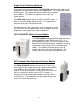
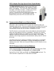
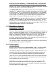
The FX3U-232ADP (pictured left) can be connected to the left
side of the PLC through the left side expansion bus. This
module requires special programming in the PLC to configure
the port. Data is transmitted and received through the use of
the RS Instruction.
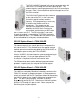
The FX2N-232IF (pictured right) connects
to the right of the PLC, in the same way
that other special function modules
connect. PLC programming is necessary
to initialize the module and set its
parameters. The module can be
configured to automatically convert data
between the ASCII that is received or
transmitted, and the binary or BCD data
that is used in the PLC. The RS instruction is not used;
instead the module is controlled by TO/FROM statements
(to be explained later). This module does not count as one
of the two additional serial ports mentioned above.
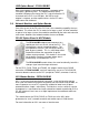
RS-232 Option Board – FX3U-232-BD
This board connects to a special port that is located on the
left side of the PLC. This method saves the special function
module space that would be occupied by the FX2N-232IF, or
the adapter space used by the FX3U-232ADP.
Like the 232ADP, this board requires special programming to
configure the port. If using an open protocol, the RS
instruction is required to transmit and receive data.
The BD board can be used for dedicated communications
protocols, requiring only the setup of the D8120 register.
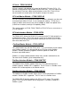
RS-422 Option Board – FX3U-422-BD
The HMI lines carried by Mitsubishi commonly connect to the
FX3U PLC through its programming port. If the programmer
needs to interface with the PLC program without disconnecting
the HMI, this board is the simplest method to accomplish this
goal. The part is plug-and-play, and adds a second
programming port to the PLC. Note that an HMI will interface
with the PLC through this port as well. Some setup of the
D8120 register may be required.