
Programming instructions

14
2.6 Special Function Modules
All of the modules that have been discussed thus far have been DISCRETE I/O
modules. The inputs or outputs are either ON or OFF. This is acceptable if all
the inputs in the PLC system are switches or simple sensors, and the outputs are
or lights to turn off and on. If it is necessary to monitor or control a temperature,
talk to a network, or control a positioning module, it is necessary to use a Special
Function Module (referred to as SFM) to accomplish these tasks. Each of these
modules has a range of internal addresses where the data is stored. The PLC
has dedicated commands to access this data.
Right Side Bus Analog Modules
There are 3 types: Analog Input modules, Analog Output modules and
Combination Analog Input/Output modules. All are used with I/O points that have
more states than just on or off. Examples of analog inputs would be a velocity
reading or pressure reading. An example of an analog output would be the
variable speed of a motor.
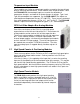
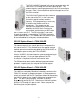
The input cards come in 2, 4, or 8 channels. These are the FX2N-2AD, FX2N-
4AD, and FX2N-8AD. The output cards come in either 2 or 4 channels. These
are the FX2N-2DA and FX2N-4DA. There are 2 combination cards. The FX0N-
3A has 2 input channels and 1 output channel. The FX2N-5A has 4 input
channels and 1 output channel. The FX3U family also has two dedicated analog
modules, the FX3U-4AD and FX3U-4DA, which are higher resolution and faster
processing modules.
All are based on varying current or voltage, usually –20 mA to +20 mA, 4-20 mA
or
–10 to + 10 V, as set by the programmer. Depending on the card, the module
receives from the PLC or from the input, a raw number (range varies by module
and type, see manuals for ranges), that is interpreted as the analog value read (if
an analog input) or the analog value to be sent out (if an analog output)
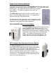
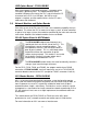
Programming Example
The PLC programmer wants to detect small changes in
pressure to control a chemical mixing process. He has a
sensor that has a range of 0 PSI to 300 PSI and generates a
voltage of –10V to +10V, and the FX2N-4AD module, which
sees –10V as the number -2000, and +10 V as +2000.
Given this information, the programmer knows that at 0 PSI
the sensor sends a voltage of –10V, which results in a value
of -2000 being written to the PLC. At 150 PSI, 0V is
generated, resulting in a value of 0 being written to the PLC.
At 300 PSI, the voltage is 10V and the PLC value is 2000. It
is the responsibility of the programmer to know what
pressure value equates to what PLC value, and to write the
program to scale that value accordingly.