
Programming instructions

99
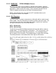
This circuit stores the error code and error step. If the D registers have been
declared to be latched registers, or the registers are in the range of D512 to
D7999, then the error information will be retained, even in the event of a power
loss
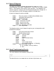
14.4 Real Time Clock Usage
The FX PLCs all have a real time clock capability. With the FX2NC, this requires
a real time clock enabled memory cassette. The data for the real time clock is
stored in D8013-D8019 as previously discussed. There are a variety of functions
which can be used to access the data in the real time clock. Some of them are
shown below. More detail on these commands can be found in Chapter 21 of the
FX3U Programming Manual.
If the registers D8013-D8019 are to be modified by commands other than the
ones below, the real time clock must be stopped. To stop the clock, turn on bit
M8015. When M8015 turns back off, the data from D8013 to D8019 is written to
the PLC’s internal real time clock. If the clock is not stopped the changes will not
take effect.
If display of a 4 digit year is desired, code can be written to write the number
‘2000’ to the year register D8018. This needs to be done on first scan every
time, so it should be triggered by M8002. It will change the display to 4 digits, but
it will not modify the year value already in the RTC.
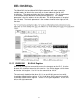
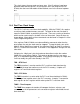
TRD – RTC Read
The TRD
instruction is used to read the PLC’s real time clock data from the
D8013-D8019 range into another area in the PLC’s memory. It copies all 7
registers to 7 consecutive data registers
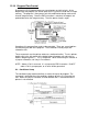
TWR – RTC Write
The TWR
instruction is used to write the PLC’s real time clock data in D8013-
D8019 range from another area in the PLC’s memory. It copies 7 consecutive
data registers to the 7 registers which make up the PLC’s real time clock.
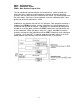
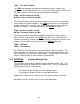
TCMP – Time Compare
The TCMP
time compare instruction will compare the hours, minutes, and
seconds as set in the parameters to 3 consecutive registers which hold the real
time clock data.