
Programming instructions

92
13.14 TO/FROM Instructions
The different types of SFMs were discussed earlier in the lesson. These
modules increase the capabilities of the PLCs. They can provide analog signal
functionality, high speed counters, or network connections just to name a few of
the options available.
For the vast majority of the SFMs it is necessary to put logic in the ladder logic
program to pass information between the CPU and the SFM. This is
accomplished through the use of TO and FROM statements.
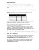
To understand TO/FROM instructions, it is important to understand the concept
of the Buffer Memory Location (BFM). Inside each SFM, there are many memory
locations that have a specific function. For example with the FX2N-4DA module
BFM #0 holds the output mode and BFM #1 holds the digital value for channel 1.
Note: Before attempting to program a SFM, it is absolutely necessary to have
the manual for that module. With out the manual it is impossible to know what
parameters need to be set, what BFMs to send the data to, or what BFMs to
receive the data from.
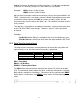
The TO instruction is used to send data from the CPU to the SFM. Typically this
data will be parameters that guide the functioning of the module or output data
for an analog output module or network communication module.
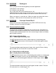
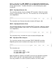
The format of the instruction:
Example:
This rung writes 1 word of data, the constant H1122, to BFM #0 (K0), in the 3
rd
SFM encountered. If the module is an FX2N-4DA, this sets channels 1 and 2 to
output 0 – 20mA, and channels 3 and 4 to output 4 – 20mA.
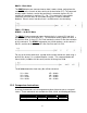
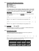
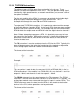
The FROM statement has the same format as the TO statement. The FROM
statement is used to move data from a BFM in an SFM to the PLC’s memory. An
analog input module stores converted data from its inputs in various BFMs. The
FROM statement moves the data from the BFMs in the module to destination
devices in the CPU, where operations can be performed.
The format of the instruction: