MITSUBISHI PROGRAMMABLE CONTROLLERS MELSEC-FX FX-Series PLC Training Manual using GX-Developer FX1S FX1N FX2N FX2NC FX3U R18-0211-SLSASG-001-F
Revisions Print Date 12/8/00 1/30/01 11/8/02 6/1/05 2/25/06 3/24/06 6/16/06 * The manual number is noted at the lower left corner of the front cover. Manual Number Revision Rev * - Created new manual, internal only Rev A - First Release Manual Rev B – Updated manual to reference GX-Developer instead of GPP-WIN. Added Section 14.5 – Finding devices. Expanded Section 15.1 to discuss how to download comments. Corrected section 15.4 from Device Label to Alias Rev C – Updated references to control products.
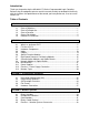
Introduction Thank you for purchasing the Mitsubishi FX-Series Programmable Logic Controller. Before using the equipment, please read this manual carefully to develop full familiarity with the functions and performance of the control you have purchased, so as to ensure correct use. Table of Contents LESSON 1 – Introduction and Overview 1.1 1.2 1.3 1.4 1.5 Course Objectives ..................................................................................... 1 Course Prerequisites .........................
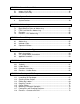
LESSON 5 – Numeric Data in PLCs 5.1 5.2 Integer (16/32 Bit) .................................................................................... 45 Decimal (16/23 Bit) .................................................................................. 47 LESSON 6 – System Devices 6. System Devices ....................................................................................... 49 LESSON 7 – Addressing 7.1 7.2 7.3 7.4 Right Side Bus Rules of Addressing .............................................
LESSON 12 – Timers and Counters 12.1 12.2 12.3 12.4 12.5 12.6 Timers...................................................................................................... 75 Counters .................................................................................................. 76 Program Examples .................................................................................. 79 Additional Timer Commands....................................................................
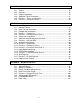
LESSON 15 – Documentation and Printing 15.1 15.2 15.3 15.4 15.5 15.6 Comments ............................................................................................. 109 Statements............................................................................................. 110 Notes ..................................................................................................... 111 Device Labels ........................................................................................
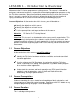
LESSON 1 – Introduction & Overview Welcome to the FX-Series programmers training course. This course is intended for designers and control engineers, responsible for developing application programs using the FX-Series controller. Apart from traditional product training in which the exclusive focus is on tools, a portion of this training is devoted to design with the intention of laying a foundation for a successful and short design and debugging cycle.
1.4 Course Description LESSON 1 - Introduction to the Course This is a brief introduction to the course, and a breakdown of the lesson topics. It is also an opportunity for students to comment on what will and will not be covered. LESSON 2 - Hardware Review This lesson discusses the hardware structure of the FX-Series logic controller, CPU module types and capabilities, Input and Output module types and characteristics.
LESSON 13 - Applied Instructions This lesson covers all special processing instructions: data manipulation instructions such as MOV, arithmetic instructions, comparison instructions, conversion instructions, logical operations, and TO/FROM instructions LESSON 14 - Diagnostic Devices – The special relays and registers that can assist in troubleshooting and writing programs are discussed here.
4
LESSON 2 – FX Series Hardware Review This lesson discusses the hardware structure of the FX-Series logic controller. This includes a review of the different CPU module types, input/output modules and interfacing variations. Lesson Objectives: At the conclusion of this lesson, you will be able to… 9 9 9 9 Explain the general sections of a PLC. Describe the different models of the FX family. Describe the characteristics of the I/O modules available.
2.2 The FX Line of PLCs Each of the PLCs in this family have certain characteristics in common: 1) An integrated power supply. Most of the PLCs in this line have a built in power supply that requires 100-240 VAC power. Several of the PLCs have a DC power version available as well. 2) Integrated I/O. The main unit has a varying number of inputs and outputs, dependent on the model chosen. The inputs are typically DC, although certain models have AC inputs as well.
FX1N This model of PLC is one of Mitsubishi’s most advanced. It provides the midrange number of I/O points similar to the FX0N, but has far more capability. It has more internal devices (like 1536 M relays and 235 counters) than the FX0N, and has motion control capability. Unlike the FX0N, the FX1N has a number of option boards that can be added to provide additional ports or allow the connection of FX0N communication modules. The FX1N-5DM can be connected to the FX1N as well.
2.3 Hardware Components Main Units FX3U (FX2N is very similar in appearance) FX2NC Base Unit The main unit contains the CPU that provides the processing power that reads the inputs, solves the logic, and writes to the outputs. The main unit contains: 1) An integrated power supply that provides power to the CPU, inputs, and a limited number of connected expansion or special function blocks 2) Integrated inputs. These can be either AC or DC, depending on the model selected.
Powered Extension Units As was mentioned previously, the FX3U is very expandable. One way to increase I/O is through the use of powered expansion units. These units have: 1) An integrated power supply, so as not to task the power supply of the main unit. AC and DC are both available. 2) Integrated inputs. 24 VDC and 120 VAC units are available. The number of inputs is either 16 or 24, depending on the model selected. 3) Integrated outputs.
Unpowered Extension Blocks The second way to expand the I/O of the FX3U system is through the use of unpowered extension blocks. These do not have a power supply, so they draw upon the power supply of the main unit or powered extension unit. As such, there is a limit (short of the I/O allocation limit for FX3Us) to the number of extension blocks that can be added. How to calculate this number will be covered later. Unpowered extension blocks for the FX3U provide 16 I/O points.
SINK or SOURCE logic refers to the voltage level that will cause the input to become active. SINK logic: the input becomes active when connected to GROUND. The S/S pin is tied to +24V.
The input trigger levels vary, depending on the module type. Generally, the input becomes active at the 2/3 level, then the input becomes inactive at the 1/3 level. For example, a +24VDC input will become active when the input voltage reaches 16VDC, and the input turns off when the voltage reaches 8VDC. 24V 16V VOLTAGE LEVEL 8V 0V OFF DIGITAL INPUT is ON ON 10mSec 10mSec The standard input point has a 10 millisecond input filter. This is done deliberately for switch de-bounce.
Integrated Outputs There are 3 different output types … • • • Relay Outputs Triac Outputs Transistor Outputs RELAY OUTPUTS Relays are dry contacts, so whatever you input on the common is switched out when the output is activated. This is the most common type of output module used. Loads up to 2 Amps, 100VAC~240VAC or 30VDCcan be switched, with a maximum of 8 Amps per Common. Most base units and extension modules have 4 outputs per common. TRIAC OUTPUTS Triacs are solid state AC switches.
2.6 Special Function Modules All of the modules that have been discussed thus far have been DISCRETE I/O modules. The inputs or outputs are either ON or OFF. This is acceptable if all the inputs in the PLC system are switches or simple sensors, and the outputs are or lights to turn off and on. If it is necessary to monitor or control a temperature, talk to a network, or control a positioning module, it is necessary to use a Special Function Module (referred to as SFM) to accomplish these tasks.
Temperature Input Modules These modules are similar to analog input modules, except for the type of input devices which can be connected. These modules have 4 input channels. With the FX2N-4AD-TC, thermocouple inputs are used for the detection of temperature changes, and work off of minute changes in voltage. Type J and Type K thermocouples are supported. On the FX2N-4AD-PT, the inputs are special platinum temperature sensors (PT-100 RTD). These sensors can detect very small temperature changes (.2°C to .
Single Axis Positioning Modules Also known as the pulse generator, the FX2N-1PG module creates a pulse train output that can be used for motion control applications. This module will accept 24VDC inputs. This module can put out a pulse train at speeds up to 100KHz. The FX2N-1PG attaches to the right side expansion bus. The FX2N-10PG module allows for 5VDC or 24VDC inputs. It offers a maximum output speed of 1MHz. This module also connects to the right side expansion bus.
FX3U Adapter Bus High Speed Pulse Output Module The FX3U-2HSY-ADP module connects to the FX3U’s left side expansion bus, and provides high speed pulse output ability, up to 200KHz. The FX3U-2HSY-ADP module does not require TO/FROM instructions. All data transmissions to and from this module are directly into the PLC’s memory. A maximum of 2 high-speed output modules can be used on an FX3U CPU. These modules must be located directly next to the CPU on the left hand side. 2.
The FX3U-232ADP (pictured left) can be connected to the left side of the PLC through the left side expansion bus. This module requires special programming in the PLC to configure the port. Data is transmitted and received through the use of the RS Instruction. The FX2N-232IF (pictured right) connects to the right of the PLC, in the same way that other special function modules connect. PLC programming is necessary to initialize the module and set its parameters.
USB Option Board – FX3U-USB-BD With recent updates to personal computers, a computer with a serial port is becoming rarer. This option board will add a standard USB port to the front of the PLC, and will allow the PC to connect to the PLC via a USB port. No USB to serial adapter is required, and the required drivers for the PC and a cable come with the board. 2.9 Network Modules and Option Boards One of the assets of the FX-series PLC line is the networking capability that can be added.
I/O Link – FX2N-16LNK-M I/O link is actually a distributed I/O system for Mitsubishi FX series PLCs. I/O modules can be placed at up to 200m from the main rack. They are addressed like standard I/O and are subject to the limitations of the CPU. Each I/O link master module can control up to 128 I/O points on up to 16 stations. CC-Link Master Module – FX2N-16CCL-M CC-Link is primarily a high powered remote I/O network, although it can be used to connect local stations as well. It uses twisted-pair cabling.
Ethernet Interface Modules – FX2NC-ENET-ADP & FX3U-ENET Ethernet is the industry standard for computer-to-computer networking. Ethernet is beginning to make its way to factory floor devices. The FX2NC-ENET-ADP can be connected to the FX1S, FX1N, FX2N, and FX2NC PLCs. All but the FX2NC will require the addition of the FX1N-CNV-BD or FX2N-CNV-BD. This is a simple serial to Ethernet gateway. GX-Developer v8.25 and later have support for the Ethernet connection to the FX Series PLCs via this module.
How to compute power drain of the power supply As has been stated before, the power supply can only support a certain number of extension block and special function blocks. In the case of the FX3U, a power supply, FX3U-1PSU-5V can be added to offer additional bus voltage. This power supply creates 1A of 5VDC and 300mA of 24VDC. It is recommended to use this module after discrete I/O extensions as they require high amounts of 24VDC. Up to 2 can be used on a single FX3U system.
TABLE 1: FX3U (16 or 32 I/O units) TABLE 2: FX3U (48 I/O or larger) TABLE 3: FX2N-32E* TABLE 4: FX2N-48E* 23
TABLE 5: 24VDC and 5VDC Supply Capacities FX3U CPU Units (AC Powered) FX3U CPU Units (DC Powered) 24
FX2N Powered Extension Units TABLE 6: Expansion Devices FX3U Option Boards FX3U Adapter Bus Modules 25
FX2N Unpowered Extension Blocks Special Function Modules 26
Special Function Modules (Continued) FX3U Display Module 27
Worksheet for Exercise 2.
2.12 EXERCISE Power Supply Calculation Using the worksheet on the previous page, combined with the preceding tables, use the steps as discussed previously, determine the power consumption of the system above. 1. Is this a valid configuration? 2. If not, why not? 3.
2.13 Memory Types The FX3U comes with enough internal RAM to hold a program of 64K steps. The 64K memory in the FX3U is NOT expandable. The FX2N comes with 8K steps of program memory. By using an 8K RAM memory module, the PLC’s memory can be expanded to 16K steps. The FX2NC comes with 8K steps of program memory. By using a 16K memory module, the PLC’s memory can be expanded to 16K steps. The FX1N comes with 8K of program memory, which is not expandable.
FLROM (Flash ROM) FLROM is permanent memory also; the program is retained with no battery required. FLROM operates similarly to EEPROM, as it is electrically erasable and can be overwritten many times. Only the FX3U uses Flash ROM. The chart below details which types of memory modules are available for each PLC type.
32
LESSON 3 – Programming Equipment This lesson discusses the hardware and software requirements to program a PLC. The student will also be shown how to connect the system together. Alternatives to using a laptop to program are also covered. Lesson Objectives: At the conclusion of this lesson, you will be able to… 9 9 9 9 List the hardware required to program a PLC with a laptop. Describe alternatives to using a laptop for programming. Describe how to connect a PLC system to a laptop.
features, as well as the ability to easily communicate over networks. It also has import capabilities to bring in programs written in older software packages. GX-DEVELOPER-FX – This is Windows based software (95, 98, NT, 2000, XP), is based on the GX-Developer software package. This software has all the features of GX-Developer, but only supports the entire FX Series and its functionality.
It is very important that the prompts are read and responded to, because this is the only opportunity to install the Import From MELSEC MEDOC features. When this prompt appears you must click on each check box to install, otherwise the programmer will be unable to import MEDOC programs in the future without first reinstalling GX-Developer. After installing GX-Developer you can browse the CD-ROM. All the manuals pertaining to GX-Developer are available in .PDF format, along with a free Acrobat viewer.
Local Device Monitor A new feature to GX-Developer, this monitor allows the programmer to monitor the states of local devices (used with the QCPU only) CAUTIONS Importing from MEDOC GX-Developer writes a temporary file during the import process. If a floppy disk is write-protected or doesn’t have enough space, the import will fail. Copying the original files to the hard drive before importing is recommended.
3.4 File Format 3.5 Hardware Connection The SC09 cable is used to connect the PLC to a personal computer for program development. The circular 8 pin port on the PLC CPU module uses the RS422 standard of communication. Most personal computers only have a RS-232 communication port. For this reason, the SC09 cable has a conversion circuit built into the connector housing. The cable includes hardware that converts from RS422 to RS232.
If the PC does not have an RS232 serial port, there are a couple of options available. • • • On the FX3U series PLC, you can install an FX3U-USB-BD and connect to the PLC directly from a USB port. For FX1S, FX1N, FX2N, FX2NC, and FX3U PLCs, you can use a cable with USB to serial converter built in. Mitsubishi offers such a cable, part number FX-USB-AW for sale. This cable has the 8-pin round DIN programming plug as found on all current FX-Series PLCs.
LESSON 4 – Numbering Systems The PLC uses several numbering systems besides the Base 10 decimal system. An understanding of these other systems is crucial to successful programming. Lesson Objectives: At the conclusion of this lesson, you will be able to… 9 9 9 Name the different numbering systems. Describe how the different systems represent numbers. Convert between number systems. Materials: 4.
To convert from binary to decimal, just add the bit values of the bits that are set to ‘1’. Bit Value 128 64 32 16 8 4 2 1 0 0 0 0 0 0 0 1 7 Bit Number 6 5 4 3 Binary Word 0000 0001 0000 0010 0000 0100 0000 1000 0000 0011 0000 0101 0000 0110 2 1 0 Decimal Value ……………… ……………… ……………… ……………… ……………… ……………… ……………… 1 2 4 8 3 5 6 With 4 bits you can count from 0 to 15 … 0000 0000 ……………… 0000 1111 ……………… 4.
4.3 Octal Numbers Octal is a Base 8 numbering system, meaning there are 8 possible values. The numbers for the octal system are 0 ~ 7. In decimal, when the count passes 9, 19, etc. the count restarts at 0, but the tens digit is incremented by one (i.e. after 9 comes 10, after 19 comes 20). In the same way, when the count passes 7 in octal, the count restarts at 0 and the tens digit is incremented. Thus after 7 comes 10, after 17 comes 20.
4.4 Binary Coded Decimal Binary coded decimal has the same counting sequence as Decimal, 0~9, but has the same format as binary. Break down each decimal digit into 4 binary bits. When converting BCD to Binary, break down each decimal digit into 4 binary bits. Decimal 26 = Bit Value 8 4 2 1 8 4 2 1 0 0 1 0 0 1 1 0 7 Bit Number 6 5 4 3 2 1 0 2 6 BCD was developed with the use of decimal devices in mind, like thumbwheels and seven segment displays.
4.5 EXERCISE Number Systems Conversion In this exercise, convert the following numbers to the given number system.
44
LESSON 5 – Numeric Data in PLCs Most PLC applications will require the handling of data, whether manipulating counter and timer values, reading data from a Special Function Module and processing then information, or high-level mathematical computations. It is critical that the programmer understand how the PLC ‘sees’ and handles the different types of data that can be encountered.
The PLC uses a numbering format known as two’s complement to display negative numbers. Two’s complement is easy to calculate: n Change all 1’s to 0’s and all 0’s to 1’s. This new number is known as the complement. o Add a 1 to the number 0111 1111 1111 1111 this is 32,767 1000 0000 0000 0000 this is the complement (the sign bit is not included in the complement but needs to be a 1 for this number to be negative) + 1 add the 1 1000 0000 0000 0001 this is –32,767.
5.2 Decimal Handling As mentioned above, the default method for handling decimals is to drop them. This restriction can be avoided through the setting of the float flag (M8023) and the use of the floating point instructions in section 5.1 of the FX3U Programming Manual. There are 2 formats for displaying decimal numbers: Scientific Notation and Floating Point Format. SCIENTIFIC NOTATION Scientific Notation uses 2 registers to store the mantissa and the exponent.
It is not possible to monitor and interpret the values in D and D+1 for Floating Point format in the same way that Scientific Notation can be monitored. The representation of floating point numbers follows a special format recommended by I.E.E.E. (Institute of Electrical and Electronic Engineers). The main advantage to using this format is the accuracy over Scientific Notation. The number pi (~3.1415926) appears as 3.
LESSON 6 – System Devices To write a program for a PLC, it is necessary to be familiar with the devices that are used in the instructions. An overview is provided here, with more detailed information to follow in later lessons. Lesson Objectives: At the conclusion of this lesson, you will be able to… 9 Name and describe the devices used to make a program. Materials: FX-Series PLC Training Manual A common question when discussing system devices is the number of each that is available to use.
If STL programming is utilized in conjunction with the IST instruction (Initial State) causes certain state relays to have special operations. 2 examples are: S0 is the manual operation return state and S2 is the automatic operation return state. One last use of state relays is as a fault annunciator. Through programming techniques described in chapter 4.4 of the FX3U Programming Manual, S900 ~ S999 can be used as user defined fault indicators.
D – Data Registers D devices are data registers. Data registers can be used for any purpose. All data registers are 16 bit, meaning the limits of numeric data is from 32768 to 32767. In ladder you can perform 32 bit operations, in that case 2 consecutive D registers are used together and the maximum numeric value can be 2,147,483,647 to -2,147,483,648. In GX-Developer, it is possible to configure D devices to be batterybacked. This means the bits will maintain their current value in the event of power loss.
V and Z – Index Registers Index registers are indicated by the symbols V and Z. V and Z can both be used for 16 bit applications, while only Z can be used with 32 bit instructions. Values stored in an index register are used as offsets to specified devices. There are 8 available V indexes (V0-V7) and 8 available Z indexes (Z0-Z7). Indexes are used by attaching their address as a suffix to an address in the program. If V or Z are referenced without a number, the number 0 is implied.
LESSON 7 - Addressing Controlling and monitoring I/O in a PLC program requires knowledge of the address of the point to be controlled. The same applies to Special Function Modules. This chapter explains how the addresses of the modules and I/O point in a system are determine Lesson Objectives: At the conclusion of this lesson, you will be able to… 9 9 9 Correctly address a discrete input or output point. Determine the address of a Special Function Module.
There are 4 different types of modules available. • Analog I/O Modules (maximum 4 per CPU) • High Speed Pulse Input Module (maximum 2 per CPU) • High Speed Pulse Output Module (maximum 2 per CPU) • Serial Communications Module (maximum 2 per CPU or 1 with a BD board) Analog Modules The data is directly input into PLC memory addresses. The modules are numbered out from the CPU to the left.
7.
7.4 EXERCISE PLC Addressing 1) A PLC system consists of an FX3U-64MR (32 I/ 32 O), 1 FX3U-4AD-ADP, an 8 point input module, 2 16-point output modules, 2 SFMs, a 16 point input module, and another SFM. Determine the addressing. 2) ARE THE FOLLOWING SYSTEMS LEGAL? WHY OR WHY NOT? A. A 64 I/O main unit (32 I/32 O), [4] 8 point input modules, [6] 8 point output modules, and [9] SFMs. B. A 128 I/O main unit (64 I/64 O), [2] SFMs, [2] 48 I/O Extension Units (24 I/24 O each), [1] 16 point input module C.
LESSON 8 – Demo Kit Layout Now that all the necessary background has been covered, it is time to take out and set up the hardware. The following section explains the demo kit and provides a brief tour of its features. Lesson Objectives: At the conclusion of this lesson, you will be able to… 9 9 Name the different parts of the kit. Know how the parts work together. Materials: 8.
8.2 Indicator Lights The PLC has indicator LEDs for its inputs and outputs. These lights are on the right side of the main unit, one set for inputs, one set for outputs. When X0 is true, LED 0 in the input section is on, when Y0 is one LED 0 in the output section is on, etc. There are 4 LEDs on the far right side of the main unit. These are status lights. • • • • Top light indicates that power is being supplied to the PLC. The 2nd LED is on when the PLC is in RUN mode, off in STOP mode.
LESSON 9 – PLC Instruction Types To write a program for a PLC, it is necessary to be familiar with the instructions that make up the PLC Instruction Set. An overview is provided here, with more detailed information to follow in later lessons. Lesson Objectives: At the conclusion of this lesson, you will be able to… 9 Describe the 3 different types of instructions.
60
LESSON 10 – Basic Instructions Basic instructions are bit control instructions, typically they make up 90% of the ladder program. They are used to confirm input status, manipulate outputs, bit shifts, and master control for nesting contacts. Lesson Objectives: At the conclusion of this lesson, you will be able to… 9 9 Name the most common basic instructions. Know the format of the instructions and what they do.
For example, a light switch is usually in the off position (non-actuated), no current is flowing (the switch is open) until someone turns it on (actuates it and energizes it). At this point, electricity starts to flow (the switch is conducting) and the lights turn on. A light switch is a normally open contact. The normally closed contact is the opposite in every respect. Current flows until the switch is actuated. A common example of this is an E-stop.
AND/OR conditions can be combined to create complex rungs of logic. Note: A rung must have an input condition, and an output to be a complete circuit. If a command is to be always on, there is a bit which can be placed in front of it, addressed M8000. This bit is always on. Connecting an output coil or bracketed instruction directly to the left power rail is not allowed. 10.3 Common Instructions SET – Bit Set RST – Bit Reset The SET instruction latches the device on.
Another method for pulsing contacts is the rising edge and falling edge pulse bits. These bits activate only for one scan similar to the PLS and PLF instructions. RISING EDGE PULSE. The rising edge pulse is a one scan pulse based on the address shown above the contact. Instead of using X003 as an input and then a PLS instruction on an M bit, this command issues a one scan pulse to the logic following it. FALLING EDGE PULSE.
10.4 EXERCISE Ladder Basics 1) X1 turns on and sets Y3. What happens to Y3 when X1 turns off? 2) What type of symbol would you use to represent a standard E-Stop in ladder logic? (Yes, E-stops are commonly hard-wired, but are often referred to in other parts of a program for various reasons) 3) List the common basic symbols (like they do. ) and describe what 4) List the common basic instructions (like PLS) and describe what they do.
66
LESSON 11 – Develop & Edit Programs Now is the time to put to work some of the knowledge that has been covered so far. In this section, we will open GX-Developer, write a simple program, download it to the PLC and test its operation, as well as investigate some of the tools in the GX-Developer software. Lesson Objectives: At the conclusion of this lesson, you will be able to… 9 9 9 9 9 9 9 Launch GX-Developer. Enter instructions to write a small program.
TOOLBARS WORKSPACE PROJECT DATA LIST The dark gray area is the workspace where the ladder logic will appear. Most of the toolbars that are open are but rarely used. These can be closed down to make the workspace larger: 1) 2) 3) 4) Under View, select Toolbar Check Standard and LD symbol, and uncheck the rest Under View find Project Data List Deselect Project Data List until required. 11.
11.3 Editing the Ladder We will now enter a basic ladder logic program. Follow the steps below to create this simple ladder program. 1) 2) 3) 4) Click on the Normally Open (NO) Contact button Type X10 into the dialog box that pops up and click OK Double-click inside the placement box The dialog box has a dropdown menu on the left. Select the Normally Closed (NC) symbol. Type X11 in the textbox and press OK. 5) Press the number 7 key. Enter Y0 in the textbox and press OK.
This is the ladder logic diagram written out in instruction list, which is the program format that the PLC actually understands. Ladder can be displayed again by going back to the View menu. Instead of Instruction List, Ladder is now displayed. You should now save the program by clicking on the Save icon in the toolbar, or by pressing Ctrl-S. Enter the Project Name as FXPROG1. Click Yes on the dialog box to save a copy of your project. 11.
Special Shortcut It may appear that this very small program takes a long time to download. This is because no matter how many ladder logic steps are in the program, GXDeveloper always downloads at least 8000 steps for the FX2N. It is possible to speed the process considerably. Be careful if using this function to ensure all code including the END statement is downloaded. 1) 2) 3) 4) 5) 6) 7) Take note of the final step number next to the rung with the END statement.
11.6 Monitor the Program Operation It is possible to view what’s happening in the program, and to check the states of program bits, in GX-Developer. This process of viewing is called Monitoring the program. 1) Click on the ‘Online’ pull down menu 2) Go to ‘Monitor’ 3) Select ‘Monitor Mode’ A small box will pop up, indicating the mode (run or stop) of the PLC and the average scan time for the program. You should notice that X10 and Y0 are not highlighted, and X11 is highlighted.
11.7 Forcing Bits and Changing Registers It can often be helpful to run sections of PLC code while writing a program. This allows the programmer to test parts of the code while the program is small enough to make changes easily. This can be done without the use of switches and other devices; all that’s required is the PLC and GX-Developer. This is called FORCING.
74
LESSON 12 – Timers and Counters Timers and counters are a standard part of a PLC program. This section will cover the various types of timers and counters available in the FX-Series PLCs as well as how to code them. Exercises will allow the user to demonstrate their understanding of the concepts.
Presets Preset is the length of time the timer runs before finishing. The preset indicates units of time bases. Thus T0 with a value of 50 runs for 5 seconds (50 x .1 seconds = 5 sec). The preset must be a number between 1 and 32,767, because timers are 16 bit registers. Timer presets can be either a K constant, or a variable, such as a data register.
16 bit counters Presets Presets are the number of times the rung driving the counter has to go through a FALSE to TRUE state transition before turning on. 16 bit counters have a range of 1 to 32,767. Counter presets can be either a K constant, or a variable, such as a data or file register. Having a D device as the preset allows an operator to make changes to the counter preset from an HMI. The accumulated value of the timer never goes above the preset value.
32 bit counters Presets Presets are the number of times the rung driving the counter has to go through a FALSE to TRUE state transition before turning on. 32 Bit counters have a range of –2,147,483,648 to 2,147,483,647. Counter presets can be either a K constant, or a variable, such as a data or file register. Having a D device as the preset allows an operator to make changes to the counter preset from an HMI, or allows the preset to be changed during operation of the logic.
12.3 Program Examples Start a new program and enter the following timer delay circuit. When developing logic, try to use the words AND and OR, for example … When X12 AND X13 are on, OR when X14 is on, then timer T0 should start timing. TIMERS by default are non-retentive. That means that they do not hold their value if the input circuit opens. Close the X14 switch and monitor the timer value (at the bottom of the monitor screen). When X14 opens, notice the timer value returns to zero.
Here is a Flip-flop circuit. Initially the T3 contact conducts, T4 coil counts up to 5 seconds. When T3 completes, T4 coil comes on. T4 contact conducts, causing the T3 coil to count up to 3 seconds. At 3 seconds the T3 coil becomes active, opening the T3 contact, which then resets T4 coil. The result is Y3 will be OFF for 5 seconds and ON for 3 seconds. Another useful timing circuit is an off-delay timer. In this example, X0 is our run signal.
A quick calculation shows that the longest time duration that can be handled by a timer is (32,767 x .1 sec / 60) = 54.36 minutes. What happens if it is necessary to run a timer longer than this? The answer uses a combination of timers and counters together like the program below: T0 runs for 1 minute. After 1 minute, T0 causes C0 to increment. After 60 increments, or 1 hour, C1 increments. After 24 hours C1 would go true and set a day counter. Note: The program shown above is not complete.
The HOUR instruction is a built-in hour meter. The function times the number of seconds the function has been active. It allows the operator to set a value for the number of hours which will turn on the output indicated in the final parameter. It is recommended that the addresses used to store the current value in hours and seconds should be in the retentive range in the PLC so they are not lost when the PLC is powered off or reset.
LESSON 13 – Applied Instructions These instructions are the ‘specialist’ instructions of the FX line. These instructions allow the PLC to perform complex data manipulations, mathematical operations, and communications. Most applied instructions work on the 16 bit or 32 bit word level. Lesson Objectives: At the conclusion of this lesson, you will be able to… 9 9 9 Name the most common applied instructions. Describe the format of the instructions and what they do.
Applied instructions by default are 16 bit instructions. If 32 bit data manipulation is desired, it is necessary to add a “D” to the front of the instruction. Example: MOV transfers 16 bits of data DMOV transfers 32 bits of data Most of these instructions continue to execute as long as the input conditions are TRUE. Sometimes this is not what is wanted.
BMOV – Block Move The BMOV block move command moves data 3 words of data starting from the source (D1) to the 3 words of data starting at the destination (D7). The command actually copies the data, so after the command is executed, registers D1-D3 contain the same data as registers D7 – D9. This command is not available specifically for 32-bit data, so the number of registers to move should be doubled. Since it moves raw data, there is no difference in the formatting.
CMP – Compare DCMP – 32-Bit Compare DECMP – Floating Point Compare The CMP compare instruction must be placed at the end of the rung. Its destination is a group of 3 bit devices, which can be Y outputs, M relays or S relays. The 3 result bits tell whether source data 1 is greater than, less than, or equal to source data 2.
INLINE COMPARISONS Unlike all the function blocks discussed so far, the inline compare instructions can be placed anywhere within the rung. They function in the same way as an input contact. These instructions are only available on the FX1S, FX1N, FX2N(C) and FX3U PLCs. These commands were not available on legacy FX PLCs. If the data register (D0) is less than the decimal constant (K10), the circuit conducts.
13.4 EXERCISE Parking Lot Write a program for the following parking lot control application: X10 indicates a car coming in X11 indicates a car going out Y0 is a sign which turns on to indicate the lot is full C200 (bi-directional 32-bit counter) will keep track of the number of cars in lot D0 will store the maximum number of cars (for this exercise write 10 to D0) When a car comes in, count that car. When a car goes out, reduce the current count by 1.
13.7 Increment and Decrement Instructions INC – Increment DINC – 32-Bit Increment DEC – Decrement DDEC – 32-Bit Decrement The increment and decrement instructions simply add or subtract 1 from the data in a 16-bit data register. These instructions execute nearly twice as fast as ADD or SUB instructions, and are not subjected to the limitations of a counter. These commands can be coded to operate on 32-bit numbers as DINC/DINCP and DDEC/DDECP.
Note how all 32-bit commands were prefixed with a D. All floating point commands are also prefixed with a D since they operate on 32-bit numbers, and the commands all begin with an E to indicate floating point format. Integer square root requires a little more explanation. The square root calculated will be a rounded number, unless floating point math is being done. If a rounded answer is produced, special relay M8021 is turned on. 13.10 EXERCISE Binary Math Please find Project #4 in the appendix.
While it is possible to use SET, RESET and the comparison instructions with high speed counters, these instructions are scan dependent and limit the benefits of high speed counters. To obtain full benefit, use the following high speed instructions. HSCS – High Speed Counter Set This instruction functions like the standard SET instruction. When the counter reaches a specified value, a bit is set. This instruction uses an interrupt and is scan independent.
13.14 TO/FROM Instructions The different types of SFMs were discussed earlier in the lesson. These modules increase the capabilities of the PLCs. They can provide analog signal functionality, high speed counters, or network connections just to name a few of the options available. For the vast majority of the SFMs it is necessary to put logic in the ladder logic program to pass information between the CPU and the SFM. This is accomplished through the use of TO and FROM statements.
13.15 EXERCISE FX2N-5A Module Access The FX3U demo cases have installed an FX2N-5A analog module. Write the TO/FROM instructions required to communicate to this module and populate the data fields as shown on the GOT screen. The list of buffer memories for the FX2N-5A module can be found in the FX2N-5A Hardware Manual. NOTE: the averaging times value from the GOT should be written to all 4 averaging times values in the module. 13.
WSFL – Word Shift Left WSFR – Word Shift Right The Word Shift Left and Word Shift Right commands will move a word (or multiple words) of data in the same way as shown above for the bit shift instructions. The command takes the same 4 parameters. The first parameter is the location of the data to be shifted into the register(s). The second parameter is the first address of the shift data. The third parameter is length of the shift data.
13.18 Program Flow Control By default the PLC program processes top to bottom and left to right. At the beginning of the program, the actual inputs on the system are read into an image memory. The program is then processed, with modifications being made to the internal image memory. Once the END instruction is reached, the outputs are updated based on the image memory. Then the process begins again. Sometimes this program flow needs to be controlled.
CALL – Call Subroutine SRET – Subroutine Return FEND – Main Routine Program End The call subroutine command allows the execution of a section of code only when activated. Unlike the jump command, execution of the main program resumes from the point where the subroutine was called. By removing code from the main ladder, scan times can be improved, since the subroutine code is only processed when the subroutine is active. Subroutines are coded at the end of a PLC program.
LESSON 14 – Diagnostic Devices No programmer is perfect, and no PLC is going to last forever. Fortunately, the FXseries PLC line has a number of dedicated relays and registers that store information, including error codes about the operation of the PLC. Lesson Objectives: At the conclusion of this lesson, you will be able to… 9 9 9 9 Identify those registers and relays that assist in troubleshooting. Interpret the information shown by the registers and relays.
14.2 Special D Registers The addresses D8000 and above are reserved for system use. In the FX1S/1N/2N/2NC, the range is D8000-D8255. In the FX3U, the range is D8000D8511. These registers have various system functions. The complete list of special D registers is found in the FX3U Programming Manual in Chapter 36. It can also be found in the GX-Developer software in the help menu. A few of the diagnostic register available D8004 Error relay active (i.e.
This circuit stores the error code and error step. If the D registers have been declared to be latched registers, or the registers are in the range of D512 to D7999, then the error information will be retained, even in the event of a power loss 14.4 Real Time Clock Usage The FX PLCs all have a real time clock capability. With the FX2NC, this requires a real time clock enabled memory cassette. The data for the real time clock is stored in D8013-D8019 as previously discussed.
TZCP – Time Zone Compare The TZCP time compare instruction will compare the hours, minutes, and seconds as set in the parameters to 2 sets of 3 consecutive registers which hold the upper and lower limits of the real time clock data to compare. HTOS – Hours to Seconds (16-Bit) DHTOS – Hours to Seconds (32-Bit) These two commands will convert a time value in hours, minutes, and seconds into a number of seconds and back.
14.6 GX-Developer Diagnostics Much of what has been discussed was necessary to troubleshoot programs in pre GX-Developer days. This information is still useful to display faults to an HMI, or to save fault codes for future examination, as in the ladder logic above. Please create a new program and enter the rung shown below: Take a moment to examine the above logic. What happens when X0 is turned on? The fixed value 4 is divided by 0 and the result is placed into D0.
Error Number 6705 is the error that appears in D8067. Step 4 is the step where the error occurs and is stored in D8069. The message Operation Error refers to Error Code 8067, which is stored in D8004. 3. 4. 5. Highlight the error by clicking on it Click on the PLC Error in the Help section. The following screen should appear: This screen explains possible causes of the error state and possible solutions.
Find Device is used to find a device address regardless of the instruction. It will search the entire program for a particular address. There are a couple of options on this screen. In the bottom left you can limit the search to the entire program, current location back to top, or current location to end of program. There is also a setting for a find option. None causes the find function to look specifically for the address entered. Digit allows the find to look for a bit address in a word of bits.
Find Contact or Coil will search the program for an address used as either a contact or a coil. In the first window, select contact or coil. Then in the right window, enter an address. This can be handy when an address has been used as a contact numerous times in a program to find the one location it was used as a coil. Replace Device allows search and replace of a device or a range of devices within the program. A single address can be specified for the earlier device and for the new device.
Replace Instruction will change one instruction type to another. The earlier instruction is the type of instruction to replace, and the new instruction is the instruction to substitute into the program. This can be useful for example to replace all occurrences of INC with INCP in a program. Change Open/Close Contact will change all occurrences of an open contact to a closed contact and change closed contacts to open. A single command will invert the state of all occurrences of the address.
Cross reference information can be displayed in one of two ways. One option is the Cross Reference List, which is a pop-up window display of the cross reference. This will sit on top of all other windows, and must be closed to move to another screen. The other is the Cross Reference Window. This windowbased display of the cross reference can be tiled, cascaded, minimized, or moved around as other windows in the workspace. It does not need to be closed to move to another screen.
List of Used Devices The List of Used Devices will show a list of the devices used in the program. The list can be configured to show a single program (FX only supports one) or all programs in the PLC (in the case of a Q-Series PLC). An address is entered in the find device box, and after pressing the Execute button, the list starting at that address is shown in the window below. There are columns which will show an asterisk (*) if that address has been used as an input or output.
GX-Developer has a built-in wizard to assist in the configuration of the data trace. Settings can also be defined manually. Once the settings are made, the trace settings are stored to a file on the PLC. That file can be read back form the PLC. The results of the trace can be uploaded once the data trace has completed. The files can also be deleted from the PLC. Once the data has been uploaded from the PLC, it can be viewed in GXDeveloper or it can be output to a .
LESSON 15 – Documentation & Printing The programs that have been written so far have been fairly simple, and you, the programmer have been present as they were written. This makes it fairly simple to troubleshoot these programs if there is a problem. Imagine if the program is 4000 steps, written by someone who left the company 2 years ago. Without any program documentation, it would be nearly impossible to troubleshoot a problem.
Important: The PLC will only hold the first 16 characters of comments. The rest of the comment will be truncated. If the programmer wants to document the program as the program is written, it is possible to have comments and one other form of documentation enabled at the same time. Go to the Tools pull-down menu, select Options, and click the box next to “Continues during Command Write” under the Device Comment Input heading. As devices are entered into the program, GX-Developer will prompt for a comment.
A statement can be up to 64 characters long. Multiple statements can be attached to a single rung to provide an in-depth description of the rung’s purpose. Statements appear to the left and on top of a rung. To enter a statement, simply press the semicolon at anytime while the rung is in edit mode. A textbox will appear, type the message and then press OK. 15.3 Notes Notes are also referred to as coil comments. Notes appear to the right of the rung, over the output coil.
15.6 Printing GX-Developer has very flexible printing capabilities. These can be accessed by clicking on the Printer Icon on the toolbar. The programmer can choose to print as much or little of the program as required. Some of the available printing options are: 1. Title – Prints a title page. Title can contain 64 characters/ line at 9 lines. Automatically includes the date of the print out 2. Ladder – Prints the Relay Ladder Logic diagram. Can choose to print out only part of the program. 3.
Here is the Print Dialog Box. Click on the tab for the method of printing desired.
114
APPENDICES 115
116
Project 1 X010 0 Y000 X011 X012 2 Y001 Y001 X013 X014 6 Y002 X015 X016 Y000 10 Y001 Y003 Y004 Y005 X017 16 Y002 Y006 Y007 20 END
Project 2 X010 K50 0 T0 K1000 T128 T0 7 Y000 T0 9 Y001 T128 11 Y002 T128 13 Y003 X011 K100 T200 15 T200 19 Y004 T200 21 Y005 X012 23 RST T200 X013 K10 26 C0 C0 30 Y006 C0 32 Y007 X014 34 37 RST C0 END
Project 3 X010 0 INC D0 INCP D0 DEC D0 DECP D0 RST D0 X011 4 X012 8 X013 12 X014 16 X015 20 26 MOV K0 D0 END
Project 4 X010 0 ADD D0 D1 D10 SUB D0 D1 D10 MUL D0 D1 D10 DIV D0 D1 D10 X011 8 X012 16 X013 24 32 END