
Hardware manual


FX1S Series Programmable Controllers Outputs 6
6-4
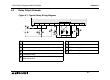
6.3 Transistor Output Examples
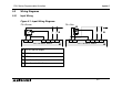
Figure 6.2: Transistor Output Wiring Diagram
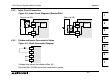
Figure 6.3: Japanese Model Transistor Output
➊
Do not use this terminal
➋
Emergency Stop
➌
Fuse
➍
External Mechanical
Interlock (See Section 6.4)
➎
DC Power Supply
➏
Reverse-current protection
diode (See Section 6.4)
➐
Inductive load
+V0 Y0 Y1 Y2 Y3+V1 +V2 Y4 Y5
➍
➎
➌
➌
➋
MC1 MC2
MC2 MC1
➊
➑➐ ➏
➏
COM0
Y0 Y1 Y2 Y3
COM1 COM2
Y4 Y5
➊
➍
➎
➌
➌
➋
MC1 MC2
MC2 MC1
➏➏
➑➐