HARDWARE MANUAL FX1S SERIES PROGRAMMABLE CONTROLLERS
FX1S Series Programmable Controllers Foreword • This manual contains text, diagrams and explanations which will guide the reader in the correct installation and operation of the FX 1S Series Programmable Controllers. It should be read and understood before attempting to install or use the unit. • Further information can be found in the FX Series Programming Manual II.
FX1S Series Programmable Controllers FX1S Series Programmable Controllers Hardware Manual Manual number : JY992D83901 Manual revision : G Date : March 2003 i
FX1S Series Programmable Controllers Guidelines for the Safety of the User and Protection of the FX1S. This manual provides information for the use of the FX1S. The manual has been written to be used by trained and competent personnel.
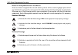
FX1S Series Programmable Controllers Notes on the Symbols Used in this Manual At various times throughout this manual certain symbols will be used to highlight points which are intended to ensure the users personal safety and protect the integrity of equipment. Whenever any of the following symbols are encountered its associated note must be read and understood. Each of the symbols used will now be listed with a brief description of its meaning.
FX1S Series Programmable Controllers • Under no circumstances will Mitsubishi Electric be liable responsible for any consequential damage that may arise as a result of the installation or use of this equipment. • All examples and diagrams shown in this manual are intended only as an aid to understanding the text, not to guarantee operation. Mitsubishi Electric will accept no responsibility for actual use of the product based on these illustrative examples.
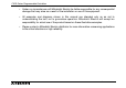
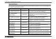
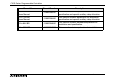
FX1S Series Programmable Controllers Associated Manuals The following manuals are recommended as essential reference material for the correct operation of a FX1S series Programmable controller. Manual Name Manual Number Description FX Programming Manual II JY992D88101 This manual contains instruction explanation about FX1S, FX1N, FX2N and FX2NC Series PLC.
FX1S Series Programmable Controllers Manual Name Manual Number Description FX1N-2AD-BD Users Manual JY992D96201 This manual contains explanation for installation, specification and special auxiliary relay allocation. FX1N-1DA-BD Users Manual JY992D96401 This manual contains explanation for installation, specification and special auxiliary relay allocation. FX1N-8AV-BD JY992D84601 This manual contains hardware explanation for installation and specification.
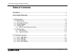
FX1S Series Programmable Controllers Table of Contents Guideline ...................................................................................................ii Associated Manuals ..................................................................................v 1. Introduction................................................................................................. 1-1 1.1 1.2 1.3 1.4 Model Name ................................................................................................
FX1S Series Programmable Controllers 3. Installation Notes........................................................................................ 3-1 3.1 3.2 3.3 3.4 3.5 3.6 3.7 3.8 Product Outline .......................................................................................................... 3-2 FX1S RUN/STOP Control .......................................................................................... 3-3 General Specifications.............................................................
FX1S Series Programmable Controllers 5. Inputs.......................................................................................................... 5-1 5.1 24V DC Input Specifications ...................................................................................... 5-1 5.2 Wiring Diagrams ........................................................................................................ 5-2 5.2.1 5.2.2 5.2.3 5.2.4 Input Wiring ................................................................
FX1S Series Programmable Controllers 7. Diagnostics................................................................................................. 7-1 7.1 7.2 7.3 7.4 7.5 7.6 7.7 7.8 7.9 7.10 Preliminary Checks.................................................................................................... 7-1 ERROR LED ON (CPU ERROR) .............................................................................. 7-2 Common Errors .......................................................................
FX1S Series Programmable Controllers 1 INTRODUCTION 1 2 TERMINAL LAYOUTS 2 3 INSTALLATION NOTES 3 4 POWER SUPPLY 4 5 INPUTS 5 6 OUTPUTS 6 7 DIAGNOSTICS 7 xi
FX1S Series Programmable Controllers 1 INTRODUCTION 2 TERMINAL LAYOUTS 3 INSTALLATION NOTES 4 POWER SUPPLY 5 INPUTS 6 OUTPUTS 7 DIAGNOSTICS xii
FX1S Series Programmable Controllers 1. Introduction 1 Introduction This manual covers the hardware installation instructions for the FX1S Series Programmable (Logic) Controller. 1 Table 1.1: AC Power, Relay Output Units MODEL INPUT QTY FX1S-10MR-ES/UL 6 FX1S-14MR-ES/UL 8 FX1S-20MR-ES/UL 12 FX1S-30MR-ES/UL 16 TYPE OUTPUT QTY TYPE POWER SUPPLY 4 Relay 8 85 - 264 VAC 75 (2.96) 90 (3.55) 75 (2.96) Table 1.
FX1S Series Programmable Controllers Introduction 1 Table 1.3: DC Power, Relay Output Units MODEL INPUT QTY FX1S-10MR-DS 6 FX1S-14MR-DS 8 FX1S-20MR-DS 12 FX1S-30MR-DS 16 TYPE OUTPUT QTY TYPE POWER SUPPLY 4 24V DC Sink / Source DIMENSIONS mm (inches) 60 (2.37) 6 24 VDC Relay 8 +10, -15% 75 (2.96) 0.22 (0.48) 90 (3.55) 49 (1.93) 100 (3.94) 14 MASS (WEIGHT) kg (lbs) 0.30 (0.66) 0.35 (0.77) Table 1.
FX1S Series Programmable Controllers Introduction 1 Figure 1.1: FX1S Outline Drawing Dimensions: mm (inches) E S /U L ,E S S /U L :7 5 (2 .9 6 ") D S ,D S S :4 9 (1 .9 3 ") W 1 W -8 (0 .3 2 ") 2 ` ` b W T Q U S u b n l k m w O w P w Q w R w S w T w V w U 2 0 1 4 5 D IN R a il: 3 5 (1 .3 7 ") 3 6 7 E R R O R e w P @ r | P S l q 3 9 0 (3 .5 5 ") P O W E R R U N 8 2 (3 .
FX1S Series Programmable Controllers Introduction 1 Table 1.
FX1S Series Programmable Controllers 1.1 Introduction 1 Model Name 1 F X 1S- 1 4 M R - E S / U L A) B) C) F) E) D) 2 3 Table 1.
FX1S Series Programmable Controllers 1.2 Introduction 1 World Specification Table 1.
FX1S Series Programmable Controllers 1.3 Introduction 1 Serial Numbers S E R I A L N O. : 9 X 3 2 6 7 1 3) 1) e.g. 9=1999 0=2000 2) 1-9 X Y Z 2 = Jan - Sept = Oct = Nov = Dec 3 4 Table 1.
FX1S Series Programmable Controllers 1.4 Introduction 1 Configuration Figure 1.
FX1S Series Programmable Controllers Introduction 1 *1 Available for use with FX1S version 2.00 or later. *2 When using the FX1N-EEPROM-8L with an expansion board in group C, only the loader function (transfer program) can be used. Remove it from the PLC after using the loader function and attach the top cover onto the PLC. 1 2 *3 GOT-F900 Series can connect via an FX1N-232-BD to the FX1S PLC.
FX1S Series Programmable Controllers Introduction 1 Table 1.9: Configuration Notes A FX1S Series Main Unit B FX1N Expansion Boards for Analog I/O C FX1N Expansion Boards without Analog I/O D Memory Cassette or Display Module E Programming Software F RS-232C/RS-422 Converter for PC G Dedicated Programming Tools H HMI Devices (GOT-F900/ GOT-A900/ DM/ DU) H' DU Series (Discontinued since Sept. 2002) Table 1.
FX1S Series Programmable Controllers 1.4.1 Introduction 1 Note for Using Expansion Board 1 The following conditions cannot be accomplished with an FX1S PLC. - FX1N-422-BD + FX-2PIF - FX1N-5DM + FX1N-422-BD + FX-10DM 2 - FX-10DM + FX1N-422-BD + FX-10DM - Connect two Programming tools (FX-10P-E, FX-20P-E, Programming software, etc.
FX1S Series Programmable Controllers 1.5 Backup Data 1.5.1 Data Backup Introduction 1 Data includes the Program, Comment, File Register (D1000 ~ D2499), and parameter data. This will be stored as long as the EEPROM is not damaged. Mitsubishi Electric has guaranteed a life cycle time of 10,000 writes to the EEPROM memory. Users may experience operational writes to the EEPROM in excess of 10,000; however, due to temperature effects a quantitative estimation cannot be given.
FX1S Series Programmable Controllers 2. Terminal Layouts 2 Terminal Layouts The following selection of terminal layouts are taken from the FX1S product range. Note: All layouts are schematic only and are intended to aid in the creation of wiring diagrams. 2.1 FX1S-**MR-ES/UL 1 2 Figure 2.
FX1S Series Programmable Controllers 2.2 Terminal Layouts 2 FX1S-**MR-DS Figure 2.
FX1S Series Programmable Controllers 2.3 Terminal Layouts 2 FX1S-**MT-DSS Figure 2.
FX1S Series Programmable Controllers 2.4 Terminal Layouts 2 FX1S-**MT-ESS/UL Figure 2.
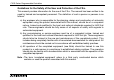
FX1S Series Programmable Controllers 3. Installation Notes 3 Installation Notes The installation of FX1S products has been designed to be safe and easy. When the products associated with this manual are used as a system or individually, they must be installed in a suitable enclosure. The enclosure should be selected and installed in accordance to the local and national standards.
FX1S Series Programmable Controllers 3.1 Installation Notes 3 Product Outline Figure 3.
FX1S Series Programmable Controllers 3.2 Installation Notes 3 FX1S RUN/STOP Control RUN or STOP of the FX1S can be controlled by: 1 !The RUN/STOP switch mounted next to the programming port. "A standard input (X0 to X17) defined by the system parameters. 2 #Remotely from a personal computer or other programming peripheral. Note:The FX1S RUN/STOP switch works in parallel with the RUN input terminal. Please refer to Table 3.2.
FX1S Series Programmable Controllers 3.3 Installation Notes 3 General Specifications Table 3.3: General Specifications Item Description Operating Temperature 0 to 55 °C (32 to 131 °F) Storage Temperature -20 to 70 °C (-4 to 158 °F) Operating Humidity 35 to 85% Relative Humidity, No condensation Storage Humidity 35 to 90% Relative Humidity, No condensation Vibration Resistance - Direct Mounting Conforms to EN 68-2-6; 10 - 57 Hz: 0.075 mm Half Amplitude 57 - 150 Hz: 9.
FX1S Series Programmable Controllers 3.4 Installation Notes 3 PLC Mounting Arrangements To prevent a rise in temperature, mount the units to walls. Never mount them to the floor or ceiling of an enclosure. Figure 3.3: PLC Mounting Diagram 1 2 A A FX 1S CPU 3 A 4 A A > 50mm(1.
FX1S Series Programmable Controllers Installation Notes 3 Caution • Units should not be installed in areas subject to the following conditions: excessive or conductive dust, corrosive or flammable gas, moisture or rain, excessive heat, regular impact shocks or excessive vibration. • Take special care not to allow debris to fall inside the unit during installation e.g. cut wires, shavings etc. Once installation is complete remove the protective paper band to prevent overheating.
FX1S Series Programmable Controllers Installation Notes 3 • Replace the terminal cover provided, after installation or wiring work is completed, and before supplying power and operating the unit to avoid electric shock. • After reading the manual’s safety instructions, initiate the operation for making program changes while the PLC is in RUN mode, forcing ON/OFF, and switching RUN/STOP. • DO NOT use the “●” terminal in PLC.
FX1S Series Programmable Controllers 3.5 Installation Notes 3 DIN Rail Mounting Units can be snap mounted to 35mm(1.37") DIN rail (DIN EN 50022). To release, pull the spring loaded clips away from the rail and slide the unit off and up. 3.6 Direct Mounting Table 3.4: Hole positions mm inches ± 0.2 ± 0.01 W A A = W-8mm (0.32") FX1S-10M✩ FX1S-14M✩ FX1S-20M✩ FX1S-30M✩ 2-∅ (→) 52 2.05 52 2.05 E S /U L ,E S S /U L :7 5 (2 .9 6 ") D S ,D S S :4 9 (1 .
FX1S Series Programmable Controllers 3.7 Installation Notes 3 Termination of Screw Terminals Terminal screws should be tightened to between 0.5 to 0.8 N$m. Terminal screws must be secured to prevent a loose connection thus avoiding a malfunction. The terminal screws for the FX1S Series PLC are M3.0. The crimp style terminal (see Figure 3.4 and 3.6) is suitable for use with these screws and should be fitted to the cable for wiring.
FX1S Series Programmable Controllers Installation Notes 3 1) Handle the crimp terminal of the following size when 1 wire is used per terminal. Refer to Figure 3.5 for installation instructions. Figure 3.4: Crimp Terminal for M3 Screws 6.2 mm (0.24" ) or less φ 3.2 (0.13") φ 3.2 (0.13") 6.2 mm (0.24") or less Figure 3.
FX1S Series Programmable Controllers Installation Notes 3 2) Handle the crimp terminal of the following size when 2 wires are used per terminal. Refer to Figure 3.7 for installation instructions. 1 Figure 3.6: Crimp Terminal for M3 6.2 mm (0.24" ) or less φ 3.2 (0.13") 6.2 mm (0.24") or less 6.3 (0.25") mm or more φ 3.2 (0.13") 2 6.3 (0.25") mm or more 3 Figure 3.
FX1S Series Programmable Controllers 3.8 Installing Optional Units 3.8.1 Expansion Boards Installation Notes 3 The following is a generic explanation of how to install an expansion board onto the FX1S PLC. For greater detail and specifications of each optional unit, please see the relevant products manual.
FX1S Series Programmable Controllers Installation Notes 3 Always make sure the power is turned off, before installing a special function board. Only one board can be used at one time, do not try to stack multiple boards. D)' E) D) C) C) A) 1 A) Special function or optional equipment board. B) Optional equipment connector port. C) M3 screw to secure board. D) Top cover for board. E) M3 screw to secure top cover. Note: Do not remove this screw. 2 3 • Remove base unit top cover.
FX1S Series Programmable Controllers 3.8.2 Installation Notes 3 FX1N-5DM Display Module Always make sure the power is turned off, before installing the 5DM. A) Top cover for DM B) Optional equipment connector. C) M3 screw to secure top cover. A) C) • Remove the base unit top cover. • Attach the top cover for DM A), and secure with screw C) (if 5DM is to be permanently mounted) B) • Plug in the 5DM at connector B) For further information please refer to the FX1N-5DM user’s manual.
FX1S Series Programmable Controllers 4. Power Supply 4.1 Wiring Techniques Power Supply 4 1 Wiring for FX1S products has been designed to be safe and easy. If the user is concerned about the correct installation of these products or associated products, please contact a professional electrician who is trained to the local and national standards applicable to the installation site. 4.
FX1S Series Programmable Controllers 4.3 Power Supply 4 Power Supply • When wiring an AC supply, the “Live” cable should be connected to the “L” terminal and the “Neutral” cable should be connected to the “N” terminal. Do NOT connect the “Live” wire to the “N” terminal, otherwise, the user may receive a dangerous shock upon powerup. • When wiring a DC supply, the “Live” cable should be connected to the “+” terminal and the “Neutral” cable should be connected to the “-” terminal.
FX1S Series Programmable Controllers 4.4 Power Supply 4 Power Supply Characteristics Table 4.1: AC Input Power Requirements, FX1S-**M*-ES/UL, ESS/UL Description Power supply Max. allowable momentary power failure period Fuse (size) rating In-rush current Power consumption 24V DC Service Supply 1 FX1S-10M FX1S-14M FX1S-20M FX1S-30M 100 - 240V AC, +10% -15%, 50/60 Hz 10ms; if less than 10ms, the PLC will continue operation. If 10ms or more, the PLC will shut down 250V 1.0A 100V AC - Max.
FX1S Series Programmable Controllers 4.5 Power Supply 4 Power Supply Wiring Figure 4.
FX1S Series Programmable Controllers Power Supply 4 Figure 4.
FX1S Series Programmable Controllers 4.6 Power Supply 4 Service Power supply An AC powered FX1S can supply a service current of 24V DC at 400mA. A DC powered FX1S does not have the capacity to supply a service current. 4.7 Earthing / Grounding Use a cable at least 0.2mm2 (AWG24) to ground equipment. Ground resistance must be less than 100Ω. Note that the ground cable must not be connected to the same ground as the power circuits.
FX1S Series Programmable Controllers 5. Inputs 5.1 24V DC Input Specifications Inputs 5 1 Table 5.1: FX1S Input Specifications 2 FX1S Main Unit X0 - X7 Input voltage 24V DC +/- 10% Input current Input switching current Response time Variable response time Circuit isolation Operation indication X10 - X17 OFF ➔ ON ON ➔ OFF 24V DC, 7mA 24V DC, 5mA >4.5mA >3.5mA <1.5mA 3 4 10ms (default) 0 - 15ms for X000-X017 via use of the FX1S digital filter.
FX1S Series Programmable Controllers 5.2 Wiring Diagrams 5.2.1 Input Wiring Inputs 5 Figure 5.
FX1S Series Programmable Controllers 5.2.2 Inputs 5 Input Circuit Connection Figure 5.2: Input Circuit Diagrams (Source/Sink) Source (-ve S/S) 1 Sink (+ve S/S) 24V 24V 24V DC 5.2.3 24V DC X X S/S 0V S/S 0V 2 3 4 Diodes and Inputs Connected in Series Figure 5.3: Diode Connection Diagram 5 24V X 6 S/S 0V 7 Voltage drop across the diode is Max. 4V. No more than 2 LEDs should be connected in series.
FX1S Series Programmable Controllers 5.2.4 Inputs 5 Resistors and Inputs Connected in Parallel Parallel resistance Rp: FX1S = 15kΩ. If resistance Rp is less than the stated value, then add the Rb value using the Equation 1 calculation. Alternatively; Current leakage: FX1S = 1.5mA. If the current leakage is greater than the stated value, then add the Rb value using the equation 2 calculation. Figure 5.4: Parallel LED Diagram 24V Eqn 1 : Rb ≤ 4Rp 15 - Rp Eqn 2 : Rb ≤ 6 I - 1.
FX1S Series Programmable Controllers 6. Outputs 6.1 Output Specifications Outputs 6 1 Table 6.1: Output Specifications Description Relay Output Transistor Output Switched voltages (resistive load) ≤ 240V AC, ≤ 30V DC 5 - 30V DC Rated current / N points (resistive load) 2A/1 point, 8A/COM 0.5A/1 point, 0.8A/COM Max. Inductive load 80VA, 120/240 VAC, See table 6.2 for more details 12W/24V DC Max. Lamp load (tungsten load) 100W (1.17A/85V AC, 0.4A/250V AC) 0.
FX1S Series Programmable Controllers 6.2 Outputs 6 Relay Output Example Figure 6.1: Typical Relay Wiring Diagram COM0 ➎ Y0 COM1 Y1 ➋ ➒ COM2 ➋ ➌ ➐ ➑ ➎ ➓ Y2 Y3 MC2 Y5 ➊ MC1 ➍ MC1 Y4 MC2 ➐ ➏ ➊ Do not use this terminal ➐ Inductive load ➋ Fuse ➑ Incandescent Lamp ➌ Reverse-current protection diode (See section 6.4) ➒ DC Power Supply ➍ External Mechanical Interlock ➓ AC Power Supply ➎ Emergency Stop abxorber (0.1µF capacitor + 100-120Ω resistor) ➏ Surge (See section 6.
FX1S Series Programmable Controllers 6.2.1 Outputs 6 Reliability Tests The test results in Table 6.2 were gathered from a 1 sec ON/OFF test cycle. Please note that the over current induced by in-rush greatly reduces the relay contact’s service life. The rated life for an inductive AC load such as a contactor or solenoid valve is 500,000 operations at 20VA. Table 6.2: Relay Life Cycle Data Description Load capacity Life of contact (cycles) Example load (Mitsubishi contactor) 20VA 0.2A/100VAC 0.
FX1S Series Programmable Controllers 6.3 Outputs 6 Transistor Output Examples Figure 6.2: Transistor Output Wiring Diagram +V0 Y0 +V1 Y1 +V2 Y2 Y3 MC1 ➐ ➎ ➑ ➏ ➋ Y5 ➊ MC2 ➍ MC2 Y4 ➊ Do not use this terminal ➋ Emergency Stop ➌ Fuse Mechanical ➍ External Interlock (See Section 6.4) ➎ DC Power Supply ➏ MC1 ➌ ➌ protection ➏ Reverse-current diode (See Section 6.4) ➐ Inductive load Figure 6.
FX1S Series Programmable Controllers 6.3.1 Outputs 6 Response Times OFF times increase as the load current decreases. For improved response times use a 'dummy' resistor, see Figure 6.4. If a response time of 0.5 ms or better is required when using 'light loads' use a 'dummy' resistor and ensure the signal line has a current greater than 60mA/24V DC. 1 2 Figure 6.
FX1S Series Programmable Controllers 6.4 Outputs 6 Applying Safe Loads Caution for DC Loads 1) Relay output case This PLC does not have any internal protection DC (+) DC (-) circuitry on the relay outputs. For switching direct Inductive load current on inductive loads, a reverse-current protection diode should be installed in parallel with the l oad. T he r el ay co n ta c t l ife d e c r e a s es Reverse-current PLC output protection diode significantly if this is not done.
FX1S Series Programmable Controllers Outputs 6 Caution for AC Loads 1 1) Relay output case This PLC does not have any internal protection circuitry on the relay outputs. For switching AC on inductive loads, a surge absorber (0.1µF + “100 to 120Ω”) should be installed in parallel with the load. The relay contact life decreases significantly if this is not done. Besides protecting the internal circuity of the PLC, a surge absorber decreases the noise emissions to the load.
FX1S Series Programmable Controllers Outputs 6 Mechanical Interlock Ensure all loads are applied to the same side of each PLC output, see previous figures. Loads which should NEVER simultaneously operate (e.g. direction control of a motor), because of a critical safety situation, should not rely on the PLC’s sequencing alone. Mechanical interlocks MUST be fitted to all critical safety circuits. (See proceeding figure.
FX1S Series Programmable Controllers 7. Diagnostics 7.1 Preliminary Checks Diagnostics 7 1 Table 7.1: Preliminary Checks 2 POWER RUN ERROR Check power supply, ground and I/O cables are wired correctly. 3 POWER RUN ERROR Turn the power supply on. Check that the power LED is lit. Down load a small test program to the PLC. Verify the program to ensure it has been written to the PLC correctly. Using the programming device, force each output ON/OFF. Check the output LEDs for operation.
FX1S Series Programmable Controllers 7.2 Diagnostics 7 ERROR LED ON (CPU ERROR) Table 7.2: Error LED Checks POWER RUN ERROR Fault ERROR LED ON Remedy Reset PLC. Turn power Possible OFF, then results ON and trigger RUN input. Remedy Power OFF A Disconnect earth/ground Possible results terminal LED is lit LED is lit A B Check for programming error. Ensure the earth/ ground cable is correctly rewired.
FX1S Series Programmable Controllers 7.3 Diagnostics 7 Common Errors - Corroded contact points at some point in an I/O line. 1 - An I/O device has been used outside its specified operating range. - An input signal occurs in a shorter time period than that taken by one program scan. 7.4 2 Maintenance - Check interior temperature of the panel. 3 - Check panel air filters if fitted. - Check for loosening of terminals or mounting facilities (due to vibration).
FX1S Series Programmable Controllers 7.5 Diagnostics 7 Operation and Error Flags Table 7.3: Operation and Error Flags M8004 (ref. 8004) Error occurance (ON when M8060-7 are ON) M8061 (ref. D8061) PLC hardware error M8035 Forced RUN mode M8063 (ref. D8063) Parallel link error M8036 Forced RUN signal M8064 (ref. D8064) Parameter error M8037 Forced STOP signal M8065 Syntax error (ref. D8065, D8069) M8039 (ref. D8039) Constant scan mode M8066 Program (circuit) error (ref.
FX1S Series Programmable Controllers 7.6 Diagnostics 7 PLC Status Registers 1 Table 7.4: PLC Status Registers D8000 Watchdog timer (default 200msec) D8001 D8002 2 PLC version 22100 = FX1S Version 1.00 22 = FX1S, 100 = Version 1.
FX1S Series Programmable Controllers 7.7 Diagnostics 7 Error Registers Table 7.
FX1S Series Programmable Controllers 7.8 Diagnostics 7 Error Codes 1 Table 7.
FX1S Series Programmable Controllers 7.9 Diagnostics 7 Instruction List Table 7.7: Numerically Sorted 000 010 020 030 040 050 060 070 080 0 PROGRAM FLOW CJ TRANSFERS, COMP CMP +-×÷, LOGICS ADD SHIFT DATA OPERATION 1 ZRST HIGH-SPEED REF HANDY INSTR.
FX1S Series Programmable Controllers Diagnostics 7 Table 7.8: Alphabetically sorted Symbol FNC No. D P ABS 155 ABSD 062 ADD 020 A ALT 066 AND' 232-238 ASCI 082 BCD 018 B BIN 019 BMOV 015 CALL 001 CCD 084 C CJ 000 CMP 010 Symbol FNC No. D P DEC 025 DECO 041 DI 005 D DIV 023 DRVA 159 DRVI 158 DSW 072 EI 004 E ENCO 042 FEND 006 F FOR 008 H I L M N O Symbol FNC No.
FX1S Series Programmable Controllers Symbol FNC No. D P PID 088 PLSR 059 PLSV 157 P PLSY 057 PRUN 081 PWM 058 RAMP 067 050 R REF RS 080 SEGL 074 SFRD 039 S SFTL 035 SFTR 034 Diagnostics 7 Symbol FNC No. D P SFWR 038 SPD 056 S SRET 002 SUB 021 TADD 162 TCMP 160 TRD 166 T TSUB 163 TWR 167 TZCP 161 Symbol FNC No.
FX1S Series Programmable Controllers 7.10 Diagnostics 7 Device List 1 Table 7.
FX1S Series Programmable Controllers Device Type Counters (C) Specification Remarks General 16 points Range: 1 to 32,767 counts C0 to C15 Type: 16 bit up counter Latched (EEPROM backed-up) 16 points Range: 1 to 32,767 counts C16 to C31 Type: 16 bit up counter Range: -2,147,483,648 to +2,147,483,647 counts General rule: Select counter combinations with a combined counting frequency of 60kHz or less.
FX1S Series Programmable Controllers Device Type Specification Remarks General 128 points D0 to D127 Type: 16 bit data storage register pair for 32 bit device Latched (EEPROM backed-up) 128 points D128 to D255 Type: 16 bit data storage register pair for 32 bit device Maximum 1500 points D1000 to D2499 set by parameter in 3 blocks of 500 program steps Type: 16 bit data storage register File Data registers (D) Pointers (P) Diagnostics 7 Externally adjusted 2 points Range: 0 to 255 D8030 & D8
FX1S Series Programmable Controllers Device Type Constants Diagnostics 7 Specification Remarks Decimal K 16 bit: -32,768 to +32,767 32 bit: -2,147,483,648 to +2,147,483,647 Hexadecima lH 16 bit: 0000 to FFFF 32 bit: 00000000 to FFFFFFFF 7-14
FX1S Series Programmable Controllers 1 INTRODUCTION 1 2 TERMINAL LAYOUTS 2 3 INSTALLATION NOTES 3 4 POWER SUPPLY 4 5 INPUTS 5 6 OUTPUTS 6 7 DIAGNOSTICS 7
FX1S Series Programmable Controllers 1 INTRODUCTION 2 TERMINAL LAYOUTS 3 INSTALLATION NOTES 4 POWER SUPPLY 5 INPUTS 6 OUTPUTS 7 DIAGNOSTICS
FX1S Series Programmable Controllers
HARDWARE MANUAL FX1S SERIES PROGRAMMABLE CONTROLLERS HEAD OFFICE: MITSUBISHI DENKI BLDG MARUNOUCHI TOKYO 100-8310 HIMEJI WORKS: 840, CHIYODA CHO, HIMEJI, JAPAN MODEL FX1S-HW-E MODEL CODE 09R510 JY992D83901G (MEE) Effective Mar. 2003 Specifications are subject to change without notice.