
User`s manual


92
FX3U Series Programmable Controllers
User’s Manual - MODBUS Serial Communication Edition
9 Slave Specification
9.4 User defined MODBUS Device Address Assignment
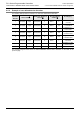
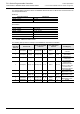
The following tables provide the values for MODBUS address allocation for Bit devices and word devices for
the example stated above:
Bit device:
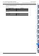
Word device:
*1. CN200 - CN207 are 32bit counters.
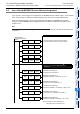
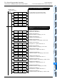
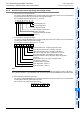
The following table provides an example of an invalid user defined device allocation.
Coils (Read / Write) FX3U Device
0x0000 - 0x001F X0 - X37
0x0020 - 0x005F M128 - M191
Holding-Register (Read / Write) FX3U Device
0x0000 - 0x0007 TS0 - TS127
0x0008 - 0x0009 CS128 - CS159
0x000A - 0x00D9 D1000 - D1207
0x00DA - 0x01D9 R0 - R255
0x01DA - 0x01E9
CN200 - CN207
*1
Device
Allocation
Data set
Device Code
Block size / Number
of Devices
PLC Head Device
Address
PLC Mapping
1 D8470(4bit) 5H(X) D8470(12bit) 2 D8471 0
Coil 0-31
→X0-X37
2 D8472(4bit) 0H(M) D8472(12bit) 4 D8473 128
Coil 32-95
→M128-M191
3 D8474(4bit) 8H(TS) D8474(12bit) 8 D8475 0
H-Register 0-7
→TS0-TS127
4 D8476(4bit)
9H(CS)
→0
D8476(12bit)
2→0
D8477
240→0
NOT MAPPED!
CS240-CS271
exceeds the valid
range for CS. Error has
occurred so the
assignment is stopped.
5 D8478(4bit)
CH(D)
→0
D8478(12bit)
13→0
D8479
1000→0
NOT MAPPED!
Skipped due to error.
6 D8480(4bit)
DH(R)
→0
D8480(12bit)
16→0
D8481
0→0
NOT MAPPED!
Skipped due to error.
7 D8482(4bit)
FH(CN)
→0
D8482(12bit)
16→0
D8483
200→0
NOT MAPPED!
Skipped due to error.
8 D8484(4bit) 0 D8484(12bit) 0 D8485 0 Unused