
User`s manual


89
FX3U Series Programmable Controllers
User’s Manual - MODBUS Serial Communication Edition
9 Slave Specification
9.4 User defined MODBUS Device Address Assignment
1
Outline
2
Specifications
3
System
Configuration
4
Wiring
5
Communication
Setup
6
Related
Devices and
Comm. Status
7
MODBUS
Standard
Commands
8
Master
Specification
9
Slave
Specification
10
Creating
Programs
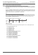
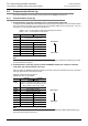
d Size (12bit): 1 to 2048 blocks.
The size of 1 block is defined for the PLC devices as follows:
Bit device (
c is 0H to BH): 1 word (16 bit devices)
D and R register (
c is CH or DH): 16 word
TN and CN 0~199 (
c is EH or FH): 1 word
32 bit counter CN 200~255 (
c is FH): 1 double word
Note
If the above range is exceeded, or the selected value exceeds the valid range for the PLC device defined in
c
a MODBUS communication error will occur.
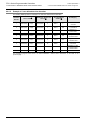
e FX3U PLC head device address (16bit)
Valid values are 0-32767 although this is dependent on the PLC device defined in
c.
Note
For the head device addresses 0H to 5H
c must be a multiple of 8. For the head device 6H to BH c these
values must be multiples of 16. If a device address is selected that is not a multiple of 8 or 16 respectively a
MODBUS communication error will occur.
X and Y addressing should always be completed in octal. i.e. 00, 20, 40 etc.
If the selected head device address or its combination with the block length exceeds the valid range for the
selected PLC device a MODBUS communication error will occur.
If the setting of
d and e is correct and the device mapping is valid, the values will be moved into the special
data registers D8470 - D8485. In the event that an error is detected, the MOV will not be executed and the
corresponding D-Register and all subsequent registers up to D8485 will be set to 0.
If an error occurs during the device allocation, mapping will be stopped at the first invalid mapping value.
However any mapping operations that have been successfully executed before the error occurrence will be
effective.
For Auxiliary Relays, Data Registers and Counters it is necessary to separate the mapping for standard and
special devices as well as 16 and 32-bit devices. According to this rule it is not possible to map standard
Auxiliary Relay (M0-M7679) and Special Auxiliary Relay (M8000-M8511) in the same mapping command.
(The same applies for Data Registers & Special Data Registers, 16-bit counters & 32-bit counters).