
User`s manual

88
FX3U Series Programmable Controllers
User’s Manual - MODBUS Serial Communication Edition
9 Slave Specification
9.4 User defined MODBUS Device Address Assignment
9.4.1 Format of the user defined device allocation
The user defined device allocation affects only the RW areas - "Coils" and "Holding Register". The mapping of
the Read Only (RO) areas "discrete inputs" and "Input Register" is fixed and cannot be changed from the
default setting.
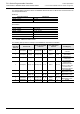
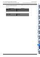
One set of configuration information requires two registers where up to eight PLC device areas can be
mapped into the MODBUS slave address area. The user defined devices are then mapped to the top of the
MODBUS address range of "coils" or "Holding Register". The PLC devices are mapped in the order given by
the device allocation data sets 1 to 8 (D8470/D8471 - D8484/D8485).
Note
The values set for D8470 - D8485 by the MOV command are checked at the initialisation phase after power
ON. If the values are valid they will be moved into the special data registers D8470 - D8485. In the event that
an error is detected, the MOV command will not be executed and the corresponding D-Register and all
subsequent registers up to D8485 will be set to 0.
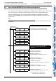
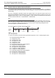
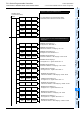
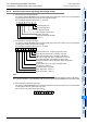
The format of the device allocation data set is as follows:
c Device code: defines which FX3U device type shall be mapped into "coils" or "Holding Register" (4bit)
0H : M (special M) mapped into "Coils"
1H : S mapped into "Coils"
2H : TS mapped into "Coils"
3H : CS mapped into "Coils"
4H : Y mapped into "Coils"
5H : X mapped into "Coils"
6H : M (special M) mapped into "Holding Registers"
7H : S mapped into "Holding Registers"
8H : TS mapped into "Holding Registers"
9H : CS mapped into "Holding Registers"
AH : Y mapped into "Holding Registers"
BH : X mapped into "Holding Registers"
CH : D (special D) mapped into "Holding Registers"
DH : R mapped into "Holding Registers"
EH : TN mapped into "Holding Registers"
FH : CN mapped into "Holding Registers"
D8470
Device code
(4bit)
1
D8471
Size
(12bit)
2
PLC head device address
(16bit)
3
MSB LSB
Device
allocation
data
Where:
MSB - Most Significant Bit
LSB - Least Significant Bit