
User`s manual


87
FX3U Series Programmable Controllers
User’s Manual - MODBUS Serial Communication Edition
9 Slave Specification
9.4 User defined MODBUS Device Address Assignment
1
Outline
2
Specifications
3
System
Configuration
4
Wiring
5
Communication
Setup
6
Related
Devices and
Comm. Status
7
MODBUS
Standard
Commands
8
Master
Specification
9
Slave
Specification
10
Creating
Programs
9.4 User defined MODBUS Device Address Assignment
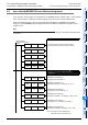
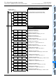
Up to eight PLC device ranges can be mapped to the MODBUS Device Address range in a user defined
order. The procedure for creating user defined mapping can be seen in the program example below.
When user defined mapping is set-up by D-registers D8470 to D8485 in the MODBUS Configuration
Program, the default MODBUS device assignment becomes invalid and mapping according to the user's
program occurs.
Note
When changing the MODBUS configuration the user must reset the power in order that new parameters are
recognised.
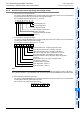
M8411
MODBUS Serial
Communication Setup
MOV
H1097 D8400
MOV
H11 D8401
MOV
H1 D8414
MOV
H11 D8415
MOV
K100 D8416
0
Program for Setting up MODBUS Slave
MOV
H5002 D8470
MOV
K0 D8471
MOV
H4 D8472
MOV
K128 D8473
MOV
H8008 D8474
Program for User Defined MODBUS Device
Assignment
MOV
K0 D8475
MODBUS Device Mapping 1
X mapped coils / Block Size = 2
MODBUS Device Mapping 2
Head Device address = 128. Mapping = M128 - M191
MODBUS Device Mapping 3
TS mapped into H - registers / Block Size = 8
MODBUS Device Mapping 3
Head Device address = 0. Mapping = TS0 - TS127
Note: For details on User defined device
assignment refer to Subsection 9.4.1
For more details on the Communication Setup
Parameters, refer to Section 5.2 of this manual.
MODBUS Device Mapping 1
Head Device address = 0. Mapping = X0 - X37
MODBUS Device Mapping 2
M mapped into coils / Block Size = 4