
User`s manual

80
FX3U Series Programmable Controllers
User’s Manual - MODBUS Serial Communication Edition
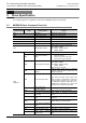
8 Master Specification
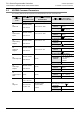
8.3 ADPRW Command Parameters
8.3 ADPRW Command Parameters
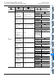
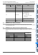
The following table shows the required command parameters for each command code.
:
Command
Code
:
Device Address/
Sub-command Code
:
Device Count/Sub-command
Data/AND Mask
/ :Source Data /
Destination PLC Device/OR Mask
Applicable Devices: D • R • indexing • K • H
1H
Read Coils
MODBUS Address:
0000H~FFFFH
Device Count:1~2000
PLC Destination Device (head address)
Applicable
Devices
D
• R • M • Y • S •
indexing
Block Length
(+ 15)
÷16
2H
Read Discrete
Inputs
MODBUS Address:
0000H~FFFFH
Device Count:1~2000
PLC Destination Device (head address)
Applicable
Devices
D
• R • M • Y • S •
indexing
Block Length
(+ 15)
÷16
3H
Read Holding
Register
MODBUS Address:
0000H~FFFFH
Device Count:1~125
PLC Destination Device (head address)
Applicable
Devices
D
• R • indexing
Block Length
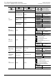
4H
Read Input
Register
MODBUS Address:
0000H~FFFFH
Device Count:1~125
PLC Destination Device (head address)
Applicable
Devices
D
• R • indexing
Block Length
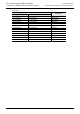
5H
Write Single Coil
MODBUS Address:
0000H~FFFFH
0 (fixed)
PLC Source Device (head address)
Applicable
Devices
D
• R • K • H • M • X •
Y
• S • indexing
0 = bit OFF
1 = bit ON
Block Length 1 Point
6H
Write Single
Register
MODBUS Address:
0000H~FFFFH
0 (fixed)
PLC Source Device (head address)
Applicable
Devices
D
• R • K • H •
indexing
Block Length 1 Point
7H
Read Exception
State
0 (fixed) 0 (fixed)
PLC Destination Device (head address)
Applicable
Devices
D
• R • indexing
Block Length 1 Point
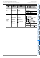
8H
Diagnosis
Sub-command Code:
0H~4H
• AH~12H
Sub-function: 0H
Loop-back Test
Sub-function Data
(loop-back data):
0~65535
Loop-back Test Data
(Slave response: echo of )
Applicable
Devices
D
• R • indexing
Block Length 1 Point
S
1
S
2
S
3
S
4
D
S
3
S
3
S
3
S
3
S
3