
User`s manual

47
FX3U Series Programmable Controllers
User’s Manual - MODBUS Serial Communication Edition
7 MODBUS Standard Commands
7.2 Frame Specifications
1
Outline
2
Specifications
3
System
Configuration
4
Wiring
5
Communication
Setup
6
Related
Devices and
Comm. Status
7
MODBUS
Standard
Commands
8
Master
Specification
9
Slave
Specification
10
Creating
Programs
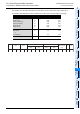
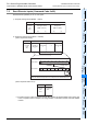
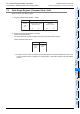
The following are calculation examples in the case where function code 01H is sent to station No. 2.
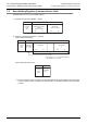
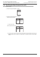
The following table illustrates the LRC calculation procedure (when sending a request message):
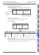
LRC in request message transmission
Station No. (address field)
Function code
Head coil number (H)
Head coil number(L)
Read points (H)
Read points (L)
02
01
00
00
00
08
0000
0000
0000
0000
0000
+0000
0010
0001
0000
0000
0000
1000
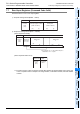
Addition result
Bit reversal 1
+1
2’s complement
0B
F4
F5
0000
1111
1111
1011
0100
1
0101
LRC (Error check) F5 F 5
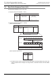
Head input number Read points
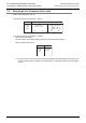
Start
:
Address field
(02
H)
Function code
(01
H)
LRC
(Error check)
(F5
H)
3A
H 30H 32H 30H 31H
(00H) (00H) (00H) (08H)
30H 30H 30H 30H 30H 30H 30H 38H 46H 35H 0DH
"CR" "LF"
0A
H