
User`s manual

35
FX3U Series Programmable Controllers
User’s Manual - MODBUS Serial Communication Edition
6 Related Devices and Communication Status
6.1 Special Data Registers
1
Outline
2
Specifications
3
System
Configuration
4
Wiring
5
Communication
Setup
6
Related
Devices and
Comm. Status
7
MODBUS
Standard
Commands
8
Master
Specification
9
Slave
Specification
10
Creating
Programs
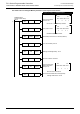
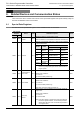
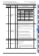
D8415 D8435
Communication
Status
Information
Setup
M,S
Defines the device range that is used to store the
communication state (event & error counter and/or event log).
R,W
*1
One MODBUS event is one byte so one 16 bit register will hold
two events. For further details refer to Subsection 9.5.1.
Note: For Event and Error Counter details refer to Section 6.4.
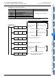
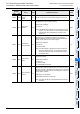
D8416 D8436
Communication
Status Device
Range Setup
M, S
Defines the PLC head device address of the device block that
will store the communication status information.
Counter values occupy 10 devices and the event log requires
33 devices. Therefore if both are displayed a total of 43 devices
are required.
According to these rules, the maximum valid range will be:
For D:
Counter only: 0-7990 (i.e. D8415 / D8435 = 01H)
Log only: 0-7967 (i.e. D8415 / D8435 = 010H)
Log and counter: 0-7957 (i.e. D8415 / D8435 = 011H)
For R:
Counter only: 0-32758 (i.e. D8415 / D8435 = 0101H)
Log only: 0-32735 (i.e. D8415 / D8435 = 0110H)
Log and counter: 0-32725 (i.e. D8415 / D8435=0111H)
Note: If the above mentioned rule is violated neither counter
nor event log is stored and an error is generated.
R,W
*1
D8417 D8437 Not used - - -
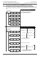
D8063 D8438
Communication
Error Code
M, S
In the event of a communication error this register holds the
error code corresponding to the error occurring during the
MODBUS communication.
Special clear conditions:
1) Power on
Note: In the event of a Ch1 error MODBUS communication
error '6321' will be stored in D8063. In the event of a Ch2
MODBUS communication error '3821' will be stored in
D8438.
R,W
*1
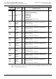
Special Data
Register
Name Valid Detailed description R / W
CH1 CH2
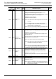
Bit No. Name
Contents
0 (bit = OFF) 1 (bit = ON)
b0
Event and error
counter
Counter values
are not stored
Counter values
are stored
b1-b3 Not used
b4
Event log
*Slave Only
Event log is not
stored
Event log is
stored
b5-7 Not used
b8
Communication
status storage
device type
D-register R-register
b9-b15 Not used