
User`s manual

32
FX3U Series Programmable Controllers
User’s Manual - MODBUS Serial Communication Edition
6 Related Devices and Communication Status
6.1 Special Data Registers
6. Related Devices and Communication Status
In this section the device numbers and functions of the special data registers and special auxiliary relays are
described for MODBUS serial communication.
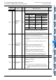
6.1 Special Data Registers
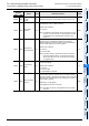
The table shows the Special Data registers used in MODBUS serial communication.
Special Data
Register
Name Valid Detailed description R / W
CH1 CH2
D8400 D8420
Communication
Format
M, S
This device sets the communication format.
Note: For details on communication format refer to Section 6.2.
R,W
*1
D8401 D8421 Protocol M, S
Selection of the channel used, RTU or ASCII mode and Master
or Slave identification.
Note: When both flags (b0 of D8401 and b0 of D8421) are
turned on, priority will be given to CH1 and CH2 will no
longer operate.
R,W
*1
D8402 D8422
Communication
Error Code
M, S
Current error code generated by the MODBUS function.
Special clear conditions:
1) Power on
2) STOP to RUN (master only)
R,W
D8403 D8423 Error Details M, S
Current error details.
Special clear conditions:
1) Power on
2) STOP to RUN (master only)
Note: Refer to the Error table in Chapter 12.
R,W
D8404 D8424
Error step
number
M
STEP number of the first ADPRW command that caused the
original error.
Special clear conditions:
1) Power on
2) STOP to RUN
Note: If the step number is greater than 32767 the value will
become a negative number. To see the step numbers
above 32767 the user must convert the step number to
an unsigned value.
R,W
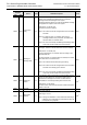
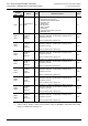
Bit No. Name
Contents
0 (bit = OFF) 1 (bit = ON)
b0
Protocol
Selection
Other communication
protocol
MODBUS
serial line
b1-3 Not used
b4
Master/ slave
setting
MODBUS Master
MODBUS
Slave
b5-7 Not used
b8
RTU/ASCII
mode setting
RTU ASCII
b9-15 Not used