
User`s manual

25
FX3U Series Programmable Controllers
User’s Manual - MODBUS Serial Communication Edition
4 Wiring
4.5 Connection Diagram for MODBUS RS-485
1
Outline
2
Specifications
3
System
Configuration
4
Wiring
5
Communication
Setup
6
Related
Devices and
Comm. Status
7
MODBUS
Standard
Commands
8
Master
Specification
9
Slave
Specification
10
Creating
Programs
4.5 Connection Diagram for MODBUS RS-485
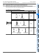
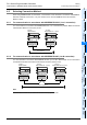
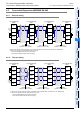
4.5.1 One-pair wiring
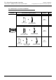
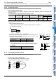
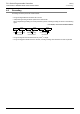
4.5.2 Two-pair wiring
Terminal
resistor:
110
Ω
Class-D grounding
(resistance: 100
Ω
or less)
*1
Class-D grounding
(resistance: 100
Ω
or less)
*1
SDA
SDB
RDA
RDB
SG
Terminal
resistor:
110
Ω
FX
3U
-485ADP-MB
Master
SDA
SDB
RDA
RDB
LINK
SG
*2 *2
FX
3U
-485ADP-MB
Slave
FX
3U
-485ADP-MB
Slave
FX
3U
-485ADP-MB
Slave
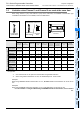
Make sure to perform Class-D grounding on the shield of the twisted pair cable connected to the FX
3U
-485ADP-MB.*1
Make sure to provide a terminal resistor at each end of a line.
The FX
3U
-485ADP-MB has a built-in terminal resistor.
Set the terminal resistor selector switch accordingly.
Class-D grounding
(resistance: 100
Ω
or less)
*1
SDA
SDB
RDA
RDB
SG
SDA
SDB
RDA
RDB
SG
*2
Terminal
resistor:
330
Ω
×
2
Class-D grounding
(resistance: 100
Ω
or less)
*1
Class-D grounding
(resistance: 100
Ω
or less)
*1
SDA
SDB
RDA
RDB
SG
SDA
SDB
RDA
RDB
SG
Terminal
resistor:
330
Ω
×
2
SDA
SDB
RDA
RDB
LINK
SG
*2 *2
*2 *2
Class-D grounding
(resistance: 100
Ω
or less)
*1
SDA
SDB
RDA
RDB
SG
FX
3U
-485ADP-MB
Master
FX
3U
-485ADP-MB
Slave
FX
3U
-485ADP-MB
Slave
FX
3U
-485ADP-MB
Slave
Make sure to perform Class-D grounding on the shield of the twisted pair cable connected to the FX
3U
-485ADP-MB.*1
Make sure to provide a terminal resistor at each end of a line.
The FX
3U
-485ADP-MB has a built-in terminal resistor.
Set the terminal resistor selector switch accordingly.
*2