
User`s manual

24
FX3U Series Programmable Controllers
User’s Manual - MODBUS Serial Communication Edition
4 Wiring
4.4 Connection Diagram for MODBUS RS-232C
4.4 Connection Diagram for MODBUS RS-232C
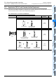
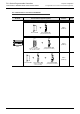
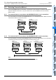
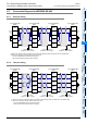
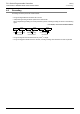
Representative wiring examples are shown in this section. When pin numbers in the counterpart equipment
are different, wire the pins as shown below.
4.4.1 Connection diagram between FX PLC and MODBUS RS-232C equipment
*1. For third-party external equipment requiring the Control Signal, connect these pins.
The FX
3U-232ADP-MB does not require these pins to be connected.
External equipment operating in accordance
with MODBUS RS-232C
Name
When CS and
RS are used
Name
When DR and
ER are used
9-pin
D-Sub
25-pin
D-Sub
9-pin
D-Sub
25-pin
D-Sub
FG
−
1FG
−
1
RD(RXD) 2 3 RD(RXD) 2 3
SD(TXD) 3 2 SD(TXD) 3 2
RS(RTS) 7 4 ER(DTR) 4 20
SG(GND) 5 7 SG(GND) 5 7
CS(CTS) 8 5 DR(DSR) 6 6
FG
RD(RXD)
PLC side
SD(TXD)
ER(DTR)
SG(GND)
DR(DSR)
Name
2
3
4
5
6
FX
3U
-232ADP-MB
9-pin D-Sub
−
*1