
User`s manual

97
FX3U Series Programmable Controllers
User’s Manual - MODBUS Serial Communication Edition
10 Creating Programs
10.1 Checking Contents of Related Devices
1
Outline
2
Specifications
3
System
Configuration
4
Wiring
5
Communication
Setup
6
Related
Devices and
Comm. Status
7
MODBUS
Standard
Commands
8
Master
Specification
9
Slave
Specification
10
Creating
Programs
10. Creating Programs
This chapter explains how to setup FX MODBUS Serial Communication and how to create programs for the
Master and Slave stations.
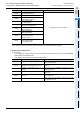
10.1 Checking Contents of Related Devices
For a full description of the PLC devices used by FX MODBUS Serial Communication, please refer to Chapter
6 of this manual.
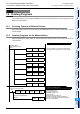
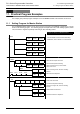
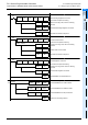
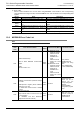
10.2 Creating Programs for the Master Station
Programs allowing the master station to read and write slave station devices can be created similar to the
example below.
M8411
MODBUS Serial
Communication Setup
MOV
H1097 D8400
MOV
H1 D8401
MOV
K2000 D8409
MOV
K400 D8410
MOV
K10 D8411
0
Program for setting up a MODBUS Master
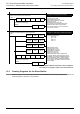
MOV
K3 D8412
MOV
H101 D8415
MOV
K100 D8416
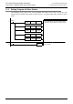
Program for Reading Coils
Slave Address: 0x02
Command Code: 0x01
MODBUS Address: 100
Device Count: 8
Destination Device Head: D0
8 coil device values starting at MODBUS
Address 100 of Slave 2 are read to the first 8
bits in D0 of the Master.
For more details on the Communication Setup
Parameters, refer to Section 5.2 of this manual.
M0
ADPRW
M8029
RST M0
Read Coils from Slave 0x02
H2 H1 K100 K8 D0
Command Complete Flag