• SAFETY PRECAUTIONS • (Always read these instructions before using this equipment.) Before using this product, please read this manual and the relevant manuals introduced in this manual carefully and pay full attention to safety to handle the product correctly. The instructions given in this manual are concerned with this product. For the safety instructions of the programmable controller system, please read the CPU module user's manual.
• CONDITIONS OF USE FOR THE PRODUCT • (1) Mitsubishi programmable controller ("the PRODUCT") shall be used in conditions; i) where any problem, fault or failure occurring in the PRODUCT, if any, shall not lead to any major or serious accident; and ii) where the backup and fail-safe function are systematically or automatically provided outside of the PRODUCT for the case of any problem, fault or failure occurring in the PRODUCT.
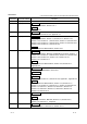
REVISIONS * The manual number is given on the bottom left of the back cover. Print Date * Manual Number Revision Apr., 2002 Jun., 2002 SH (NA)-080271-A First edition SH (NA)-080271-B Correction Operating Instructions, Section 6.12.1 Addition Section 6.12.2 Sep., 2002 SH (NA)-080271-C Correction Section 6.12.1, Section 6.12.2, Appendix 2.3 Nov., 2003 SH (NA)-080271-D Correction Operating Instructions, Section 1.1, Section 2.1.6, Section 2.2.1, Section 2.2.2, Section 6.1.1, Section 6.2.
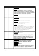
Print Date * Manual Number Aug., 2005 SH (NA)-080271-I Revision Model Addition FX3UCPU Addition Generic term and Abbreviations, Section 2.2.1, Section 2.2.2, Section 2.3, Section 2.4, Section 5.1.4, Section 8.2.1, Section 8.2.2, Section 8.3.1, Section 8.3.2, Section 8.4.1, Section 8.5.1, Section 8.6.1, Section 8.6.2, Section 8.7.1, Section 8.8.1, Section 8.9.1, Section 8.10.1, Section 8.10.2, Section 8.12.1, Section 8.12.2 Nov., 2006 SH (NA)-080271-J Correction Section 1.1, Section 2.1.6, Section 2.
Print Date * Manual Number Dec., 2008 SH (NA)-080271-N Revision Model Addition Q00UCPU, Q00UJCPU, Q01UCPU, Q10UDHCPU, Q10UDEHCPU, Q20UDHCPU, Q20UDEHCPU, FX3GCPU New Addition Appendix 9 Correction Operating Instructions, Generic term and Abbreviations, Section 2.2.1, Section 2.2.2, Section 2.3, Section 2.4, Section 5.1.2, Section 6.1.1, Chapter 7, Section 8.2.1, Section 8.2.2, Section 8.3.1, Section 8.3.2, Section 8.3.3, Section 8.4.1, Section 8.4.2, Section 8.5.1, Section 8.5.2, Section 8.6.
Print Date * Manual Number May, 2011 SH (NA)-080271-R Revision New Addition Section 2.1.9, Section 6.4, Section 6.15, Section 8.3.4, Section 8.12 Correction Section 6.4 to 6.13 changed to Section 6.5 to 6.14, Section 6.14 to 6.17 changed to Section 6.16 to 6.19, Chapter 7, Section 8.2.1, Section 8.2.2, Section 8.3.1, Section 8.3.2, Section 8.3.3, Section 8.4.1, Section 8.4.2, Section 8.5.1, Section 8.5.2, Section 8.7.1, Section 8.7.2, Section 8.8.1, Section 8.8.2, Section 8.9.1, Section 8.9.
OPERATING INSTRUCTIONS This section gives explanation of instructions in the following order.
(b) On Windows 95, communication using the COM port, e.g. computer link communication or CPU COM communication, will cause a memory leak. Therefore, do not perform continuous operation. R (3) Precautions for the use of Microsoft Windows Millennium Edition Operating System It is not recommended to use MX Component with the "system restoring function" made invalid by the operating system.
(b) If MX Component is uninstalled first on the OS1 side, the control DLLs and ACT folders are deleted. In this case, MX Component may not operate properly or cannot be uninstalled on the OS2 side. Install MX Component again on the OS2 side to operate MX Component properly or uninstall it on the OS2 side. (3) About start menu When you have uninstalled MX Component, the item may remain in the start menu. In that case, restart the IBM-PC/AT compatible personal computer.
(4) Precautions for the use of Q4ARCPU The redundant function cannot be used. (5) Restrictions on use of the FXCPU (a) When the FXCPU is used, access to the TN devices (timer present values) or CN devices (counter present values) is not permitted if the device numbers specified are split across 199 or earlier and 200 or later. (b) As the FXCPU does not have a PAUSE switch as the programmable controller CPU, an error is returned if remote pause is specified in SetCpuStatus.
(2) Precautions for GX Simulator communication Before executing the monitor utility, communication setting utility or user program, make sure that GX Simulator and GX Developer are operating. In addition, do not terminate the GX Simulator and GX Developer while the user program is running. If you do so, you will not be able to terminate the user program normally.
(5) Unlocking password when using QJ71E71 The range where the password can be unlocked by remote operation is up to the connection target station. If the password is set also on the lower layer, communication cannot be made with the programmable controller CPU on the lower layer. Starting source Enter password to unlock. AAAA Ethernet 2) QCPU 1) (Q QJ71 QJ71 mode) E71 E71 Ethernet QCPU 3) (Q QJ71 mode) E71 QCPU 4) (Q QJ71 mode) E71 QCPU 5) (Q QJ71 mode) E71 No.
(d) When two different communication systems (protocols) are used to make access from one IBM-PC/AT compatible to one Q series-compatible E71, two station numbers, i.e. for TCP/IP and for UDP/IP, must be set. However, it is not required to set different station numbers for TCP/IP and UDP/IP when using MX Component Version 3 or later and Q series-compatible E71 with serial No. 05051 or later.
Instructions for the use of MELSECNET(II), MELSECNET/10 and MELSECNET/H (1) About relaying from the MELSECNET/10 loaded station When the module is loaded to the AnNCPU or AnACPU, it is recognized as a MELSECNET(II) module. When the connected station is the AnNCPU or AnACPU, set the relayed network as MELSECNET(II). In addition, set the station number to "0" when making access to the control station.
Instructions for modem communication (1) Simultaneous modem communications It is not allowed to simultaneously perform modem communications using MX Component and other application such as GX Developer. Do not perform a modem communication using other applications during a modem communication using MX Component. If modem communications are simultaneously performed using MX Component and other application, this will result in a communication error, disconnection of telephone line or similar problem.
Instructions for programming (1) About sample programs, test programs and sample sequence programs (a) Sample programs, test programs The sample programs are attached for your reference to create user programs. The test programs are attached to conduct communication tests. Use these programs on your own responsibility. (b) Sample sequence programs The sample sequence programs attached to MX Component must be modified depending on the system configuration and parameter settings.
Instructions for use of Microsoft Excel R (1) Precautions for starting multiple Excel files on Windows Me Note that Windows Me has been confirmed to stop if you run multiple Excel files which use many control objects. * This phenomenon is not attributable to this product.
Instructions for use of Microsoft Access R (1) Precautions for the use of Microsoft Access R (a) When you paste the ACT control to an Access form and double-click the ACT control or select the custom control in the property, the following error message will appear but this does not affect the operation of ACT control. (Other error message may appear.) (b) When you paste the ACT control and display the properties, the property names displayed may be broken.
INTRODUCTION Thank you for choosing the Mitsubishi MELSOFT series Integrated FA software. Read this manual and make sure you understand the functions and performance of MELSOFT series thoroughly in advance to ensure correct use. CONTENTS SAFETY PRECAUTIONS................................................................................................................................A- 1 CONDITIONS OF USE FOR THE PRODUCT .........................................................................................
3.3 PLC Monitor Utility Operating Procedure .................................................................................................. 3- 6 4 OPERATIONS COMMON TO UTILITIES 4- 1 to 4- 3 4.1 Starting the Utility ....................................................................................................................................... 4- 1 4.2 Exiting the Utility...............................................................................................................................
6.9 CC-Link G4 Communication...................................................................................................................... 6-57 6.9.1 Switch settings of CC-Link G4 module............................................................................................... 6-57 6.9.2 Accessing procedure........................................................................................................................... 6-59 6.10 CPU Board Communication ..................................
8.6 For MELSECNET/10 Communication....................................................................................................... 8-22 8.6.1 Accessible devices .............................................................................................................................. 8-22 8.6.2 Accessible ranges ............................................................................................................................... 8-24 8.7 For CC-Link Communication .........................
APPENDICES APP- 1 to APP-62 Appendix 1 Concept of the Routing Parameters........................................................................................APP- 1 Appendix 2 How to Start the Internet/Intranet Environment ......................................................................APP- 4 Appendix 2.1 Operating procedure.........................................................................................................APP- 4 Appendix 2.2 Conditions of usable personal computers............
MANUALS The following lists the manuals for this software package. Refer to the following table when ordering manuals. Related Manuals Manual Name MX Component Version 3 Operating Manual (Startup) Explains procedures for installing and uninstalling MX Component and for browsing the operating manual. (Sold separately) MX Component Version 3 Programming Manual Explains the programming procedures, detailed explanations and error codes of the ACT controls.
HOW TO USE THIS MANUAL "HOW TO USE THIS MANUAL" is given purpose-by-purpose for the use of MX Component. Refer to the following outlines and use this manual. (1) To know the features (Section 1.1) Section 1.1 gives the features. (2) To know the system configurations (Sections 2.1, 2.2) The system configurations using MX Component are provided. (3) To know the MX Component operating environment and usable programmable controller CPUs (Sections 2.3, 2.4) Section 2.
GENERIC TERMS AND ABBREVIATIONS Unless otherwise started, this manual uses the following abbreviations and terms for the explanation of MX Component.
Generic Term/Abbreviation QSCPU FXCPU Motion controller CPU C Controller CPU Programmable controller CPU C24 UC24 QC24 QC24N QC24(N) Q series-compatible C24 L series-compatible C24 FX extended port Computer link module (Serial communication module) E71 QE71 Q series-compatible E71 Ethernet module CC-Link G4 module CC-Link IE Field Network Ethernet adapter module A6TEL Q6TEL GOT GOT1000 A - 27 Description Abbreviation for a safety CPU module (QS001CPU) Generic term for FX0CPU, FX0SCPU, FX0NCPU, FX1CPU, F
Generic Term/Abbreviation Computer link communication (Serial communication) Ethernet communication CPU COM communication CPU USB communication MELSECNET/10 communication MELSECNET/H communication CC-Link IE Controller Network communication CC-Link IE Field Network communication CC-Link communication CC-Link G4 communication CPU board communication Q series bus communication GX Simulator communication GX Simulator2 communication Modem communication Gateway function communication GOT transparent communicatio
Generic Term/Abbreviation R Windows 7 Windows Vista R R Windows XP R Visual Basic .NET Visual C++ .
MEANINGS AND DEFINITIONS OF TERMS The terms used in this manual have the following meanings and definitions. (1) Logical station number The connection target information necessary to open the communication line is combined into one data using the communication setup utility, and that data is provided with a logical number. This number may be used with the utility setting type only. (Example) For CPU COM communication Q25HCPU (CPU to communicate with) IBM-PC/AT compatible Q25HCPU MELSECNET/H (Network No.
1 OVERVIEW MELSOFT 1 OVERVIEW MX Component is a tool designed to implement communication from an IBM-PC/AT compatible personal computer to the programmable controller without any knowledge of communication protocols and modules. Use of common functions has made it extremely easy to develop serial communication and Ethernet communication programs which had been troublesome and complex.
1 OVERVIEW MELSOFT (4) Device monitor function Utilizing the PLC monitor utility enables you to monitor the status of the specified device and change its data. *1 1 X39 is ON. X39 is ON! MX Component Device status is checked. Set and connect communication path on MX Component. *1: Device data of the QSCPU cannot be changed.
1 OVERVIEW MELSOFT (7) Multithread communication Access to the same communication path can be made from multiple threads at the same time. User program Thread 1 Thread 2 Act control 1 Act control 2 (8) GX Simulator or the simulator function of GX Works2 (GX Simulator2) for offline debugging *4 By using GX Developer and GX Simulator or the simulation function of GX Works2, you can perform debugging on a single IBM-PC/AT compatible without connecting the programmable controller.
1 OVERVIEW MELSOFT (9) A wide variety of programming languages supported MX Component supports VBScript and VBA as well as Visual Basic and Visual C++ . R R (a) Creation of monitoring page using VBScript 1) Monitoring page can be created in HTML format Using the text editor, you can create a graphical monitoring home page (HTML format). You need not purchase Visual Basic , Visual C++ or like. R R Monitoring using Internet Explorer MX Component Web browser Internet Explorer 5.
1 OVERVIEW MELSOFT (b) VBA-driven data collection and monitoring function Programming using VBA allows Excel or Access functions to be utilized to create an application for providing a real-time graph display. You can log the device data of the programmable controller and collect/save the device data in real time. (10) Compatibility with multi-CPU system of QCPU (Q mode) Setting the communication setting utility or ACT control properties enables access to the multi-CPU system.
1 OVERVIEW MELSOFT (12) Accessibility to gateway devices of GOT Using the gateway function communication of MX Component can read/write the gateway device data of the GOT. Reading/writing the gateway device data of the GOT can read/write the device data of the programmable controller CPU that is being monitored by the GOT. MX Component Gateway device data of GOT can be read/written using MX Component (gateway functions). Ethernet GOT GOT GOT Programmable controller CPU data are read/written with GOT.
2 SYSTEM CONFIGURATIONS MELSOFT 2 SYSTEM CONFIGURATIONS This chapter explains the system configurations, operating environment and usable CPUs of MX Component. 2.1 System Configuration List 2 This section lists the systems that may be configured for each operating system. 2.1.1 When using Windows NT Workstation Operating System Version 4.0 R The following table lists the systems that may be configured for the use of Windows NT Workstation 4.0.
2 SYSTEM CONFIGURATIONS MELSOFT 2.1.2 When using Windows 95 Operating System R The following table lists the systems that may be configured for the use of Windows 95.
2 SYSTEM CONFIGURATIONS MELSOFT 2.1.3 When using Windows 98 Operating System R The following table lists the systems that may be configured for the use of Windows 98.
2 SYSTEM CONFIGURATIONS MELSOFT 2.1.4 When using Windows 2000 Professional Operating System R The following table lists the systems that may be configured for the use of Windows 2000 Professional. R Item Description Computer link communication Ethernet communication CPU COM communication CPU USB communication (Refer to POINT 2).
2 SYSTEM CONFIGURATIONS MELSOFT 2.1.5 When using Windows Millennium Edition Operating System R The following table lists the systems that may be configured for the use of Windows Me.
2 SYSTEM CONFIGURATIONS MELSOFT 2.1.6 When using Windows XP Professional Operating System R The following table lists the systems that may be configured for the use of Windows XP Professional. R Item Description Computer link communication Ethernet communication CPU COM communication CPU USB communication MELSECNET/10 communication (Refer to POINT.
2 SYSTEM CONFIGURATIONS MELSOFT 2.1.7 When using Windows XP Home Edition Operating System R The following table lists the systems that may be configured for the use of Windows XP Home Edition.
2 SYSTEM CONFIGURATIONS MELSOFT 2.1.8 When using Windows Vista Operating System R The following table lists the systems that may be configured for the use of Windows Vista .
2 SYSTEM CONFIGURATIONS MELSOFT 2.1.9 When using Windows 7 Operating System R The following table lists the systems that may be configured for the use of Windows 7.
2 SYSTEM CONFIGURATIONS MELSOFT 2.2 System Configuration for the Use of Each Connection Form This section provides the system configurations for the use of MX Component on a communication form basis. For details and precautions on each communication form, refer to Section 2.2.2. 2.2.
2 SYSTEM CONFIGURATIONS MELSOFT IBM-PC/AT compatible GX Developer + GX Simulator (offline debugging) GX Simulator communication Simulation function of GX Works2 (GX Simulator2) GX Simulator2 communication Modem communication Gateway function communication Modem Telephone line GOT transparent USB, RS-232 communication Ethernet GX Works2 Version 1 (SW1DNC-GXW2-E) or later Must be purchased separately A6TEL,Q6TEL,FXCPU,QC24N, Q series-compatible C24, L series-compatible C24 Modem Ethernet Etherne
2 SYSTEM CONFIGURATIONS MELSOFT 2.2.2 Details of the communication forms The table at top right of each communication format explanation indicates whether the communication format can be made up when the OSes are used. (Example) Windows NT Workstation 4.0, Windows 95, and 64-bit Windows 7 are not supported. Windows 98, Windows 2000 Professional, Windows Me, Windows XP, Windows Vista , and 32-bit Windows 7 are supported.
2 SYSTEM CONFIGURATIONS MELSOFT 2) About connection of usable modules When a computer link module is used to make access from the IBMPC/AT compatible to the programmable controller CPU, note that three are restrictions on the modules connectable directly to the IBM-PC/AT compatible. If the module cannot be connected directly to the IBM-PC/AT compatible, it may be used as the "n"th module of multidrop.
2 SYSTEM CONFIGURATIONS MELSOFT (c) Switch settings of the computer link module For the switch settings for the use of MX Component, refer to "Section 6.1.1 Switch settings of computer link modules". (d) Cable for connection For the connection cable, refer to the manual of your computer link module. Refer to Appendix 3 for cable pin assignment. POINT Only the RS-232 connector may be used for connection of the IBM-PC/AT compatible and computer link (serial communication) module.
2 SYSTEM CONFIGURATIONS MELSOFT (c) Switch settings of the Ethernet module For the switch settings for the use of MX Component, refer to "Section 6.2.1 Switch settings of Ethernet modules". 2) In case of using Built-in Ethernet port QCPUs NT 95 98 2000 Me XP Vista 7(32) 7(64) For the way to make connection to the Built-in Ethernet port QCPU, refer to the manual of your Built-in Ethernet port QCPU.
2 SYSTEM CONFIGURATIONS MELSOFT 2) Cables for connection of ACPU, QnACPU or FXCPU The following cables are needed to make communications between the IBM-PC/AT compatible and ACPU, QnACPU or FXCPU. IBM-PC/AT Compatible Side (RS-232C Cable) RS-232C/RS422 Converter Programmable controller Side (RS-422 Cable) For ACPU, QnACPU or FX1/FXU/FX2CCPU FX-232AW F2-232CAB-1*1 (When connector of IBM-PC/AT compatible is D-sub 9-pin) FX-422CAB (0.3m/0.98feet) FX-422CAB-150 (1.5m/4.
2 SYSTEM CONFIGURATIONS MELSOFT 5) USB cable and function expansion board (FX3U, FX3UC compatible) a) System configuration FX-USB-BD USB cable (packed) b) If "Operate communication setting" is checked on the <> tab in the [FX Parameter] dialog box of GX Developer, the corresponding port cannot be used for communication with the programmable controller.
2 SYSTEM CONFIGURATIONS MELSOFT 6) Function expansion board for FXCPU Series Function expansion board FX3U, FX3UC FX3U-422-BD FX3G FX3G-422-BD FX2N FX2N-422-BD FX1S, FX1N FX1N-422-BD If "Operate communication setting" is checked on the <> tab in the "FX Parameter" dialog box of GX Developer, the corresponding port cannot be used for communication with the programmable controller.
2 SYSTEM CONFIGURATIONS MELSOFT 7) RS-232 cable and function expansion board (special adaptor) for FXCPU Serial port shape of personal computer Series FX3U, FX3UC FX3G D sub 9 pin FX2N FX1NC, FX2NC FX1S, FX1N FX3U, FX3UC FX3G D sub 25 pin FX2N FX1NC, FX2NC FX1S, FX1N Required function expansion board and special adaptor FX3U-232-BD 1 Function expansion board (FX3U-***-BD) + FX3U-232ADP* FX3G-232-BD FX3G-CNV-ADP + FX3U-232ADP FX0N-232ADP + FX2N-CNV-BD FX2N-232-BD FX2NC-232ADP + FX2N-CNV-BD FX0N-232AD
2 SYSTEM CONFIGURATIONS MELSOFT When the CPU type of the project is the FX3G or FX3U(C), the channel specification (CH1/CH2) combo box is displayed. When using the FX3U-232-BD or the first FX3U-232ADP connected to the FX3U-CNV-BD, set CH1 and check the settings. When using the FX3U-232ADP connected to other than the FX3UCNV-BD or the second FX3U-232ADP connected to the FX3U-CNV-BD, set CH2 and check the settings.
2 SYSTEM CONFIGURATIONS MELSOFT (4) CPU USB communication NT 95 98 2000 Me XP Vista 7(32) 7(64) (a) Precautions 1) Windows 98, Windows 2000 Professional, Windows Me, Windows XP, Windows Vista , Windows 7 may be used when the USB driver has been installed. 2) When using Windows 2000 Professional, Windows XP, Windows Vista , Windows 7, the user must install the USB driver.
2 SYSTEM CONFIGURATIONS MELSOFT (5) MELSECNET/10 communication NT 95 98 2000 Me XP Vista 7(32) 7(64) (a) Precautions 1) Always use any of the following communication drivers. Other communication drivers cannot be used. Used OS SW2DNF-MNET10 SW3DNF-MNET10 Windows NT Workstation 4.
2 SYSTEM CONFIGURATIONS MELSOFT (8) CC-Link IE Field Network communication NT 95 98 2000 Me XP Vista 7(32) 7(64) (a) Precautions 1) As the communication driver, always use SW1DNCCCIEF-J, SW1DNC-CCIEF-B or later. Any other communication driver is unusable. 2) For details of the supported operating system of the network board to be used for communication, refer to the manual of each network board.
2 SYSTEM CONFIGURATIONS MELSOFT 3) The following are the CPUs that can be accessed by the communication drivers. SW2DNF-CCLINK SW3DNF- CCLINK SW4DNF-CCLINK-B CPU Type A to V *1 W to *2 A to V *1 W to *2 A to V *1 SW1DNCCCBD2-B W to *2 - ACPU (including motion controller CPU) QCPU(A mode) QnACPU QCPU(Q mode) LCPU : Accessible, *3 : Inaccessible *1: For ROM versions "A" to "V" of CC-Link board *2: For ROM versions "W" and later of CC-Link board *3: For Version 1.
2 SYSTEM CONFIGURATIONS MELSOFT (11) CPU board communication NT 95 98 2000 Me XP Vista 7(32) 7(64) (a) Precautions 1) Always use any of the following communication drivers. Other communication drivers cannot be used. Used OS SW0DNF-ANU-B SW1DNF-ANU-B Windows NT Workstation 4.
2 SYSTEM CONFIGURATIONS MELSOFT (13) GX Simulator communication NT 95 98 2000 Me XP Vista 7(32) 7(64) When making GX Simulator communication, use GX Developer and GX Simulator of the following versions or later. Used OS Windows NT Workstation 4.
2 SYSTEM CONFIGURATIONS MELSOFT (15) Modem communication NT 95 98 2000 Me XP Vista 7(32) 7(64) (a) Precautions 1) When performing modem communication, make the setting in the parameters and sequence program for the connected module. Use any of the following GX Developers to set the corresponding module.
2 SYSTEM CONFIGURATIONS MELSOFT (16) Gateway function communication NT 95 98 2000 Me XP Vista 7(32) 7(64) (a) Gateway function-compatible GOT For the gateway function-compatible GOT, refer to the Operating Manual (Gateway Functions) of the GOT. (b) About GOT setting and setting between GOT and programmable controller For the GOT setting and the setting between the GOT and programmable controller, refer to the Operating Manual (Gateway Functions) of the GOT.
2 SYSTEM CONFIGURATIONS MELSOFT 2.3 Operating Environment The following table summarizes the operating environment for MX Component. Item Computer Description IBM PC/AT compatible personal computer 133MHz or more Pentium *1 IBM PC/AT compatible personal computer where the OS operates. R PC CPU module MELSEC-Q series compatible PC CPU module (CONTEC CO., LTD.
2 SYSTEM CONFIGURATIONS MELSOFT Item Description Programming language Visual Basic R Development software Microsoft Visual Basic 6.0 (English version), Microsoft Visual Basic .
2 SYSTEM CONFIGURATIONS MELSOFT POINT (1) When Windows XP, Windows Vista or Windows 7 is used, the following new functions cannot be used. If any of the following new functions is used, this product may not operate normally. Start of application in Windows compatible mode Fast user switching Remote desktop Big fonts (Details setting of Screen properties) 64-bit Windows XP and 64-bit Windows Vista are not supported. When Windows 7 is used, the following new functions cannot be used.
2 SYSTEM CONFIGURATIONS MELSOFT 2.4 Usable Programmable Controller CPUs The usable programmable controller CPUs are given below.
2 SYSTEM CONFIGURATIONS MELSOFT MEMO 2 - 33 2 - 33
3 OPERATION PROCEDURES MELSOFT 3 OPERATION PROCEDURES This chapter explains the selection of the MX Component development type and the procedures for creating user applications. 3.1 Selecting the Development Type When using MX Component to create user applications, choose the utility setting type or program setting type before creating a user application. The utility setting type and program setting type will be described.
3 OPERATION PROCEDURES MELSOFT 3.2 User Application Creating Procedures 3.2.1 When using Visual Basic 6.0/Visual Basic .NET R R The following creation procedures assumes use of Visual Basic 6.0/ Visual Basic .NET. R R Power on the IBM-PC/AT compatible and start Windows. 3 Install MX Component. Make settings using the utility setting type? Refer to the operating manual (startup).
3 OPERATION PROCEDURES MELSOFT 3.2.2 When using Visual C++ 6.0/Visual C++ .NET R R The following creation procedures assumes use of Visual C++ 6.0/Visual C++ .NET. R R Power on the IBM-PC/AT compatible and start Windows . Install MX Component. Make settings using the utility setting type? Refer to the operating manual (startup). No Yes Start the communication setup utility and make communication settings in accordance with the wizard. Refer to Section 5.1, Chapter 6.
3 OPERATION PROCEDURES MELSOFT 3.2.3 When using VBA The following creation procedures assumes use of VBA. Power on the IBM-PC/AT compatible and start Windows . Install MX Component. Make settings using the utility setting type? Refer to the operating manual (startup). No Yes Start the communication setup utility and make communication settings in accordance with the wizard. Refer to Section 5.1, Chapter 6.
3 OPERATION PROCEDURES MELSOFT 3.2.4 When using VBScript The following creation procedures assumes use of VBScript. Power on the IBM-PC/AT compatible and start Windows . Install MX Component. Make settings using the utility setting type? Refer to the operating manual (startup). No Yes Start the communication setup utility and make communication settings in accordance with the wizard. Refer to Section 5.1, Chapter 6.
3 OPERATION PROCEDURES MELSOFT 3.3 PLC Monitor Utility Operating Procedure The following is the PLC monitor utility operating procedure. Start Use utility setting type? No Yes Start the communication setup utility and make communication settings in accordance with the wizard. Refer to Section 5.1, Chapter 6. After the transfer setting screen has appeared, choose the program setting type. Start PLC monitor utility.
4 OPERATIONS COMMON TO UTILITIES MELSOFT 4 OPERATIONS COMMON TO UTILITIES This chapter explains the operations common to the utilities. 4.1 Starting the Utility Each utility can be started by clicking the corresponding icon in the [Start]-[Programs *1] -[MELSOFT Application]-[MX Component] menu. For the registered icons, refer to the operating manual (startup). *1: [All programs] appears when using Windows XP, Windows Vista or Windows 7. R R R Starts Communication Setup Utility.
4 OPERATIONS COMMON TO UTILITIES MELSOFT (From the previous page) < Windows Vista > R < Windows 7 > R 2) The left screen appears for administrator users. Selecting "Allow" or Yes enables to execute a program in administrator authority. Selecting "Cancel" or No disables the execution. (3) Setting to always execute programs as an administrator To always "execute programs as an administrator", set as follows. (The procedure also applies to PLC Monitor Utility).
4 OPERATIONS COMMON TO UTILITIES MELSOFT 4.2 Exiting the Utility To exit each utility, click Exit at bottom right of the screen. As the dialog box appears, click Yes to exit the utility. Click! 4.3 Confirming the Version To confirm the version of each utility, click the [Help]-[About] menu.
5 UTILITY OPERATIONS MELSOFT 5 UTILITY OPERATIONS This chapter provides how to operate the communication setup utility and PLC monitor utility. POINT Refer to "CHAPTER 6 COMMUNICATION SETTING EXAMPLES OF THE UTILITY SETTING TYPE" for communication setting examples using the communication setup utility. 5.1 Communication Setup Utility This section describes how to operate and set the communication setup utility used to make communication with the utility setting type.
5 UTILITY OPERATIONS MELSOFT 5.1.1 Operations on target setting screen This screen is used to display the setting details of the logical station number set on the communication setting wizard and to edit. 1) 5 Item Logical station number Description Select to display the setting details and the logical station number to be edited set on the communication setting wizard. Wizard Used to start the communication setting wizard and set the logical station number.
5 UTILITY OPERATIONS MELSOFT 5.1.2 Operations on list view screen This screen is used to list the logical station numbers registered, edit the logical station number, and list the properties necessary for the program setting type. 1) Item 1) (Property list) Description Shows the settings of the registered logical station numbers. Double-clicking the logical station number starts the communication setting wizard. Wizard Used to start the communication setting wizard and set the logical station number.
5 UTILITY OPERATIONS MELSOFT 5.1.3 Operations on connection test screen This screen is used to conduct a communication test on the logical station number registered. Item Logical station number Description Select the logical station number on which a communication test will be made. Set how many times the communication test will be repeated for the specified logical station Communication diagnosis number. (Default: 5) count Setting range: 1 to 32767 Used to start (stop) the communication test.
5 UTILITY OPERATIONS MELSOFT 5.1.4 Operations on com setup import screen The communication settings saved in the file by the operations in Section 5.1.5 are reflected on the utility. This screen is used when the communication settings made on the other IBM-PC/AT compatible are to be reflected on the IBM-PC/AT compatible being used. (1) Selected menu item Select the [Menu]-[COM setup import] on the menu bar.
5 UTILITY OPERATIONS MELSOFT 5.1.5 Operations on com setup export screen The communication settings being made on the IBM-PC/AT compatible are saved in a file. (The file where data are saved is called the ACT registered file.) This screen is used to reflect the communication settings on the other IBM-PC/AT compatible. POINT Uninstalling deletes all the settings within "Communication Setup Utility". To avoid this, export the file storing the settings.
5 UTILITY OPERATIONS MELSOFT 5.1.6 Operations on communication setting wizard screens These screens are used to set the logical station number necessary to make communication with the utility setting type. (1) Outline of the communication setting wizard The logical station number necessary to make communication with the utility setting type is set in the wizard format. The places and descriptions of the settings made on the communication setting wizard screens will be given below.
5 UTILITY OPERATIONS MELSOFT (3) Explanation of the communication setting wizard screens Communication setting wizard screens are shown from wizard 1) to wizard 6) in the order. The following explains the communication setting wizard screens in the displayed order. POINT (1) The displays or available setting items of the communication setting wizard screens change with the communication settings. Set all available setting items being displayed.
5 UTILITY OPERATIONS MELSOFT (From the previous page) Wizard 2) 2) Select the "PC side I/F" to communicate with. The items shown in "Communication setting" change with the setting made in "PC side I/F". Set all available setting items and click Next> . The choices corresponding to the communications in "PC side I/F" are indicated below.
5 UTILITY OPERATIONS MELSOFT (From the previous page) Wizard 4) 4) Wizard 4) differs in available setting items depending on the settings on Wizard 2) and Wizard 3). Set all available setting items and click Next> . REMARK When the modem is selected on Wizard 2), the line setting screen appears on Wizard 3) and Wizard 4). For details of the line setting screen, refer to "Section 5.1.7 Operations on line setting screen".
5 UTILITY OPERATIONS MELSOFT When the registration of the logical station number is completed on the communication setting wizard, the settings are displayed on the target setting screen.
5 UTILITY OPERATIONS MELSOFT 5.1.7 Operations on line setting screen This screen is used to make the telephone line settings necessary to set modem communication in the communication settings utility. (1) Connect Line screen Set the line connection system, telephone line, AT command, etc. Item Description Set the line connection system. When the Q Series Corresponding C24 is used, any of the following items can be selected. (Fixed to "Auto line connect" when the A6TEL, Q6TEL, FXCPU or QC24N is used.
5 UTILITY OPERATIONS MELSOFT Item Description Set the line type. (Default: Tone) Item Line type Line Description Pulse Select this item when using dial line. Tone Select this item when using push button dial line. ISDN Select this item when using ISDN line. Set the outside line access number. Outside line number Setting range: 10 characters Setting characters: 0, 1, 2, 3, 4, 5, 6, 7, 8, 9, -, Port ,# Set the COM port for modem communication.
5 UTILITY OPERATIONS MELSOFT (2) Call book screen Set the telephone numbers used on the line setting screen. 1) Item Description 1) (Registered phone number Displays the group names and other end names. display list) Choice display Displays the settings of the other end selected in the registered phone number display list. Close Used to update the edited data and close the call book screen. Cancel Used to discard the edited data and close the call book screen.
5 UTILITY OPERATIONS MELSOFT (3) Call number setting, call number editing screens Set the telephone number to be registered to the phone book. Item Group name Destination name Description Displays the group name of the registration destination. Enter the other end of the telephone number to be registered. Setting range: 50 characters Set the telephone number. Call number Setting range: 50 characters Setting characters: 0, 1, 2, 3, 4, 5, 6, 7, 8, 9, -, ,# Set the outside line access number.
5 UTILITY OPERATIONS MELSOFT (4) AT command registration screen Set the AT commands used on the line setting screen. 1) Item 1) (Registered AT command display list) Choice display Description Displays a list of titles of the registered AT commands. Used to display the registered data selected in the registered AT command display list. Close Used to update the edited data and close the AT command registration screen.
5 UTILITY OPERATIONS MELSOFT (5) New AT command registration, AT command editing screens Register a new AT command and edit the AT command. Item Group name Title Description Displays the group name where the AT command to be registered. Enter the title of the AT command to be registered. Setting range: 60 characters Enter the AT command for modem initialization. AT command Setting range: 70 characters Setting characters: ASCII code Help of AT command 5 - 17 Used to display the AT command help.
5 UTILITY OPERATIONS MELSOFT (6) Detail setting screen Set details for telephone line connection. Make settings according to the modem used. Item Description Set the line connection CD signal confirmation time. (Default: 90) Line connection CD signal Increase the set time if the CD signal does not turn ON within the set time depending on the wait time line-connected region (example: overseas).
5 UTILITY OPERATIONS Item MELSOFT Description Set the AT command/password cancellation retry count. (Default: 3) AT command/password Increase the set count if the AT command cannot be sent or the password cannot be cancellation retry count cancelled. Setting range: 1 to 999 Set the Line callback cancel wait time.
5 UTILITY OPERATIONS MELSOFT 5.2 PLC Monitor Utility This section explains how to operate and set the PLC monitor utility. 5.2.1 Operations on transfer setting screen This screen is used to set connection from the IBM-PC/AT compatible to the programmable controller CPU. (1) Selected menu item Select [Online]-[Transfer setup] on the menu bar. (This screen also appears when the PLC monitor utility is started.
5 UTILITY OPERATIONS MELSOFT (b) When choosing the program setting type Item Program setting type Description Select when the program setting type is used to create programs. Used to start the communication setting wizard and make transfer setting. When the logical station number where the modem communication data have been set is selected, the following screen appears after OK is clicked. When you have set the password, enter the password and click OK .
5 UTILITY OPERATIONS MELSOFT POINT When the program setting type is selected, clicking the programmable controller or personal computer sketch enables you to change the details of the transfer setting. Clicking the screen portion where you want to change setting enables a setting change.
5 UTILITY OPERATIONS MELSOFT 5.2.2 Operations on device batch screen This screen is used to monitor only the specified one type of devices. 1) 2) 3) 4) Item Device Description Enter the device name to be batch-monitored. Start monitor ( Stop monitor ) Used to start (stop) monitor. Set the monitor format. (Default: Bit & Word) Item Monitor format Description Bit & Word Sets the monitor screen to the bit and word display. Bit Sets the monitor screen to the bit display only.
5 UTILITY OPERATIONS MELSOFT Item Description Set the order in which the bit devices being monitored are arranged. Bit order Item Description F-0 Arranged in order of F, E, ... 1, 0 from left to right. 0-F Arranged in order of 0, 1, ... E, F from left to right. Shows the device statuses. 1) (Monitor screen) Clicking the device name shows the device write screen. For details of the device write screen, refer to "Section 5.2.5 Operations on device write screen".
5 UTILITY OPERATIONS MELSOFT 5.2.3 Operations on buffer memory screen This screen is used to monitor only the specified one type of buffer memory. 1) 2) 3) 4) Item Description Module I/O Type the first address of the module to be monitored. Memory address Enter the address of the buffer memory to be monitored in hexadecimal or decimal. Start monitor ( Stop monitor ) Used to start (stop) monitor. Set the monitor format.
5 UTILITY OPERATIONS MELSOFT Item Description Set the order in which the bit devices being monitored are arranged. Bit order 1) (Monitor screen) 2) (Target CPU name) 3) (Communication path information) 4) (Logical station number) Item Description F-0 Arranged in order of F, E, ... 1, 0 from left to right. 0-F Arranged in order of 0, 1, ... E, F from left to right. Shows the buffer memory status. Shows the communication target CPU name specified on the communication setting wizard screen.
5 UTILITY OPERATIONS MELSOFT 5.2.4 Operation on entry device screen This screen is used to monitor the specified devices on a single screen at the same time. 1) 2) 3) 4) Item Description Used to register the device to be monitored. Clicking Register device shows the following screen. Item Device Description Type the device to be registered. Set the value to be entered when a word device is specified. (Default: DEC) Value Item DEC HEX Description Sets to decimal. Sets to hexadecimal.
5 UTILITY OPERATIONS Item 1) (Monitor screen) 2) (Target CPU name) 3) (Communication path information) 4) (Logical station number) MELSOFT Description Shows the device statuses. Clicking the device name shows the device write screen. For details of the device write screen, refer to "Section 5.2.5 Operations on device write screen". Shows the communication target CPU name specified on the communication setting wizard screen.
5 UTILITY OPERATIONS MELSOFT 5.2.5 Operations on device write screen (1) Selected menu item Select [Online]-[Device write] on the menu bar. [Device write] cannot be chosen when the QSCPU is connected. (2) Dialog box This screen is used to change the ON/OFF of a bit device or the present value of a word device or buffer memory. This screen is displayed by double-clicking the monitor screen of the corresponding tab. Item Device Bit device Description Enter the device name.
5 UTILITY OPERATIONS MELSOFT 5.2.6 Operations on clock setting screen This screen is used to read or change the clock data of the programmable controller. (1) Selected menu item Select [Online]-[Set time] on the menu bar. (2) Dialog box 1) When the QCPU (Q Mode) or LCPU is connected. 2) When the QSCPU is connected Clock data of the QSCPU cannot be changed. Item Description PC Time Shows the time of the personal computer. (Write disabled) PLC Time Shows the time of the programmable controller CPU.
5 UTILITY OPERATIONS MELSOFT 5.2.7 Operations on telephone line connection, disconnection screens Connect and disconnect the telephone line for modem communication. (1) Menu to be selected (a) Telephone line connection Select [Online] - [Connect] on the menu bar. * [Connect] cannot be chosen when the QSCPU is connected. (b) Telephone line disconnection Select [Online] - [Disconnect] on the menu bar. * [Disconnect] cannot be chosen when the QSCPU is connected.
5 UTILITY OPERATIONS MELSOFT MEMO 5 - 32 5 - 32
6 COMMUNICATION SETTING EXAMPLES OF THE UTILITY SETTING TYPE MELSOFT 6 COMMUNICATION SETTING EXAMPLES OF THE UTILITY SETTING TYPE This chapter explains the setting procedure and setting example of each communication path when the utility setting type is used for programming. POINT • For the settings other than “As set by user”, set the value as shown in the table. • Before attempting to communicate with MX Component for the first time, check if MX Component can communicate normally using GX Developer.
6 COMMUNICATION SETTING EXAMPLES OF THE UTILITY SETTING TYPE MELSOFT IBM-PC/AT compatible Module 1 Module 2 FX-485PC-IF 6 6-2 6-2
6 COMMUNICATION SETTING EXAMPLES OF THE UTILITY SETTING TYPE MELSOFT (1) C24, UC24 Settings Switch *1 Mode setting switch Station number setting switches Main channel setting Data bit setting For 1:n communication For 1:1 communication Station 0 Station 1 1 (format 1) A (format 1) 5 (format 1) 0 0 (As set by user) OFF (RS-232) OFF (RS-232) ON(8) Transmission speed setting Transmission Parity bit yes/no setting specifications Even parity/odd parity setting setting Stop bit setting switches S
6 COMMUNICATION SETTING EXAMPLES OF THE UTILITY SETTING TYPE MELSOFT (3) Q series-compatible C24, L series-compatible C24 (a) For 1:1 communication Item Settings Set Value b15 to b8 b7 to b0 CH1 communication speed CH1 transmission setting Switch 2 — CH1 communications protocol 0000H Switch 3 CH2 communication speed CH2 transmission setting 0000H Switch 4 — CH2 communications protocol 0000H Switch 1 Switch 5 Module station number 0000H 0000H When the communication protocol is set t
6 COMMUNICATION SETTING EXAMPLES OF THE UTILITY SETTING TYPE MELSOFT (b) For 1:n communication 1) Station 0 Item Switch 1 Settings b15 to b8 CH1 communication speed — Switch 2 Switch 3 CH2 communication speed — Switch 4 Switch 5 b7 to b0 CH1 transmission setting CH1 communications protocol CH2 transmission setting CH2 communications protocol Set Value Independent operation 07E6H 0008H 07E7H 0000H Module station number 0000H (As set by user) Settings Set Value Synchronous operation 2) Station 1
6 COMMUNICATION SETTING EXAMPLES OF THE UTILITY SETTING TYPE MELSOFT (4) FX extended port Set the FXCPU parameters with GX Developer before using FX extended port to perform communication. Carry out either of the following two setting methods. • To use the PLC parameters • To write values to special data registers (D8120, D8121, D8129) in a sequence program. (For FX0NCPU, only this method is applicable.) The following shows the setting items.
6 COMMUNICATION SETTING EXAMPLES OF THE UTILITY SETTING TYPE MELSOFT (b) Settings by writing values to the special data registers (D8120, D8121, D8129) in a sequence program.
6 COMMUNICATION SETTING EXAMPLES OF THE UTILITY SETTING TYPE MELSOFT 2) D8121 (Station No. setting) Specify the station No. The station No. can be specified in the range of 00H to 0FH b15 to D8121 b0 Station No. range: 00H to 0FH 3) D8129 (Time out judge time setting) Specify the FXCPU time out judge time in 10ms units. The setting range is as follows: For FX0N, FX1S, FX1N(C), FX3G, and FX3U(C), 1 to 255 (10 to 2550ms). For FX2N(C), 1 to 3276 (10 to 32760ms). If "0" is stored, 100ms is set.
6 COMMUNICATION SETTING EXAMPLES OF THE UTILITY SETTING TYPE MELSOFT 6.1.2 Accessing procedure The procedure for making access to the programmable controller CPU using computer link communication will be explained in the following order. START When using the C24, UC24 or QC24(N), set the mode and transmission setting switches. When using the Q series-compatible C24, set the software switches. When using the FX extended port, set the PLC parameters. Refer to Section 6.1.2 (2).
6 COMMUNICATION SETTING EXAMPLES OF THE UTILITY SETTING TYPE MELSOFT (2) Making the switch settings of the computer link module (a) For 1:1 communication Settings Item Set Value b15 to b8 b7 to b0 CH1 communication speed CH1 transmission setting *1 Switch 2 — CH1 communications protocol 0000H Switch 3 CH2 communication speed CH2 transmission setting *1 0000H Switch 4 — CH2 communications protocol 0000H Switch 1 Switch 5 0000H Module station number 0000H *1: Settings of CH1 and CH2
6 COMMUNICATION SETTING EXAMPLES OF THE UTILITY SETTING TYPE MELSOFT (b) For 1:n communication Settings Switch (Switch Number) Mode setting switch Module 1) CH1 side CH2 side 0 5 (format 5) 5 (format 5) ON (synchronous operation) OFF (independent operation) Station number setting switches Operation setting switch (SW01) 1 OFF (independent operation) CH2 side 3 ON (8 bit) ON (8 bit) Parity bit yes/no setting (SW03) ON (yes) ON (yes) Even parity/odd parity setting (SW04) OFF (odd) OFF (odd
6 COMMUNICATION SETTING EXAMPLES OF THE UTILITY SETTING TYPE MELSOFT (3) Setting the logical station number (Setting on communication setting wizard) Logical station number setting will be described using the system example for 1:n communication. 1) Start the communication setup utility and select the communication setting wizard. 2) Type "1" in Logical station number and click Next> . 3) Make settings as indicated below and click Next> .
6 COMMUNICATION SETTING EXAMPLES OF THE UTILITY SETTING TYPE MELSOFT (From the previous page) 5) Make settings as indicated below and click Next> . Station type Network Network type : Other station : C24 : Multidrop(combine) 6) Make settings as indicated below and click Next> . CPU type Station No : Q2A :3 7) Enter a comment and click Finish .
6 COMMUNICATION SETTING EXAMPLES OF THE UTILITY SETTING TYPE MELSOFT (4) Checking the logical station number settings (Conducting a communication test) Check whether the computer link communication settings are correct or not, using the logical station number set in (3). 1) Display the "Target setting" tab screen and select the logical station number "1". Check whether the logical station number settings are correct or not.
6 COMMUNICATION SETTING EXAMPLES OF THE UTILITY SETTING TYPE MELSOFT 6.2 Ethernet Communication (In case of using Ethernet interface modules) This section provides the procedure for Ethernet communication with the Ethernet interface module and its setting example using the utility setting type. 6.2.1 Switch settings of Ethernet modules This section gives the switch settings of Ethernet modules for the use of MX Component.
6 COMMUNICATION SETTING EXAMPLES OF THE UTILITY SETTING TYPE MELSOFT 6.2.2 Accessing procedure The procedure for making access to the programmable controller CPU using Ethernet communication will be explained in the following order. START Set the Ethernet module switches. Refer to Section 6.2.1 Set the Ethernet module parameters. Refer to Section 6.2.2 (3), (4). Connect the Ethernet module and IBM-PC/AT compatible. Refer to Chapter 2. Edit the HOSTS file.
6 COMMUNICATION SETTING EXAMPLES OF THE UTILITY SETTING TYPE MELSOFT (1) System examples The following system examples are used in this section. (a) Q series-compatible E71 system example IBM-PC/AT compatible Logical station number of "2" is used. Network No. 1 Station number: 2 Q series-compatible E71 (192.168.0.2) Station number: 2 CPU1 Q02HCPU CPU2 Q02HCPU Q series-compatible E71 (192.168.0.1) Station number: 1 Network No. 2 Q series-compatible E71 (192.168.0.
6 COMMUNICATION SETTING EXAMPLES OF THE UTILITY SETTING TYPE MELSOFT (3) Making parameter setting Parameter setting may either be made from the network parameter "MELSECNET/ETHERNET setting screen" of GX Developer or from a sequence program. The network parameters of GX Developer must be used to set the Q seriescompatible E71 (TCP/IP, UDP/IP) or QE71 (UDP/IP), or a sequence program used to set the QE71 (TCP/IP) or E71 (TCP/IP, UDP/IP).
6 COMMUNICATION SETTING EXAMPLES OF THE UTILITY SETTING TYPE MELSOFT (b) QE71 1) For TCP/IP The QE71 requires an initial processing and communication line open processing sequence program for the use of TCP/IP. The sequence program example is given below. Setting Item Set Value Setting Item TCP/IP open system 8000H (TCP, fixed buffer send) QE71's IP address 192.168.0.
6 COMMUNICATION SETTING EXAMPLES OF THE UTILITY SETTING TYPE MELSOFT (From the previous page) 6 - 20 6 - 20
6 COMMUNICATION SETTING EXAMPLES OF THE UTILITY SETTING TYPE MELSOFT 2) For UDP/IP For the QE71, set the network type, first I/O No., network No., group No., station number and IP address on the Ethernet parameter setting screen of GX Developer when using UDP/IP.
6 COMMUNICATION SETTING EXAMPLES OF THE UTILITY SETTING TYPE MELSOFT (c) E71 The E71 requires an initial processing and communication line open processing sequence program. The sequence program example is given below. 1) For TCP/IP Setting Item Set Value Setting Item TCP/IP open system 8000H (TCP, fixed buffer send) E71's IP address 192.168.0.
6 COMMUNICATION SETTING EXAMPLES OF THE UTILITY SETTING TYPE MELSOFT (From the previous page) 6 - 23 6 - 23
6 COMMUNICATION SETTING EXAMPLES OF THE UTILITY SETTING TYPE MELSOFT 2) For UDP/IP Setting Item Set Value Setting Item UDP/IP open system 100H (UDP, fixed buffer send) E71's IP address 192.168.0.
6 COMMUNICATION SETTING EXAMPLES OF THE UTILITY SETTING TYPE MELSOFT (From the previous page) *1 *1 In the communications enabled status, the E71's RUN LED is lit and the RDY LED flickers. *1: This sample sequence program represents a setting example for simultaneous broadcast. When the E71 on the programmable controller side is the AJ71E71 or A1SJ71E71-B2/B5, the "simultaneous broadcast" function is not supported. In such a case, specify the following address in "Communication address setting".
6 COMMUNICATION SETTING EXAMPLES OF THE UTILITY SETTING TYPE MELSOFT (4) Making routing parameter setting (a) Q series-compatible E71 Set the Q series-compatible E71 in "Ethernet parameter setting" of GX Developer. For the concept of the routing parameters, refer to "Appendix 1 Concept of the Routing Parameters". CPU to Be Set Setting Screen Example CPU1 CPU2 (b) QE71 Set the QE71 in "Ethernet parameter setting" of GX Developer.
6 COMMUNICATION SETTING EXAMPLES OF THE UTILITY SETTING TYPE MELSOFT (6) Setting the logical station number (Setting on communication setting wizard) Logical station number setting will be described using the system example for Q series-compatible E71. 1) Start the communication setup utility and select the communication setting wizard. 2) Type "2" in Logical station number and click Next> . 3) Make settings as indicated below and click Next> .
6 COMMUNICATION SETTING EXAMPLES OF THE UTILITY SETTING TYPE MELSOFT (From the previous page) 5) Make settings as indicated below and click Next> . Station type Network : Other station : Ethernet 6) Make settings as indicated below and click Next> . CPU type Network No Station No Multiple CPU : Q02(H) :2 :3 : None 7) Enter a comment and click Finish .
6 COMMUNICATION SETTING EXAMPLES OF THE UTILITY SETTING TYPE MELSOFT (7) Checking the logical station number settings (Conducting a communication test) Check whether the computer link communication settings are correct or not, using the logical station number set in (6). 1) Display the "Target setting" tab screen and select the logical station number "2". Check whether the logical station number settings are correct or not.
6 COMMUNICATION SETTING EXAMPLES OF THE UTILITY SETTING TYPE MELSOFT 6.3 Ethernet Communication (In case of using Built-in Ethernet port CPUs) This section provides the procedure for the Ethernet communication with the Built-in Ethernet port CPU and its setting example using the utility setting type. 6.3.1 Accessing procedure The procedure for making access to the programmable controller CPU using Ethernet communication will be explained in the following order.
6 COMMUNICATION SETTING EXAMPLES OF THE UTILITY SETTING TYPE MELSOFT (1) System example The following system example is used in this section. IBM-PC/AT compatible Logical station number of "17" is used. IP address (10.97.19.177) Built in Ethernet port CPU Q04UDEH (2) Setting parameters (In case of connection by specified Host (IP address only) Parameter setting may be made from the PLC parameter of GX Developer.
6 COMMUNICATION SETTING EXAMPLES OF THE UTILITY SETTING TYPE MELSOFT (4) Setting the logical station number (Setting on communication setting wizard) Logical station number setting will be described using the example for using the Built-in Ethernet port CPU (Q04UDEH) system example for (1). 1) Start the communication setup utility and select the communication setting wizard. 2) Type "17" in Logical station number and click Next> .
6 COMMUNICATION SETTING EXAMPLES OF THE UTILITY SETTING TYPE MELSOFT (From the previous page) 6) Make settings as indicated below and click Next> . Check the check box "Ethernet port direct connection". 7) Make settings as indicated below and click Next> . Station type CPU type Multiple CPU : Host station : Q04UDEH : None 8) Enter a comment and click Finish .
6 COMMUNICATION SETTING EXAMPLES OF THE UTILITY SETTING TYPE MELSOFT (5) Checking the logical station number settings (Conducting a communication test) Check whether the Ethernet communication settings are correct or not, using the logical station number set in (4). 1) Display the "Target setting" tab screen and select the logical station number "17". Check whether the logical station number settings are correct or not. 2) Display the "Connection test" tab screen and set the logical station number "17".
6 COMMUNICATION SETTING EXAMPLES OF THE UTILITY SETTING TYPE MELSOFT 6.4 Ethernet Communication (In case of using CC-Link IE Field Network Ethernet adapter module) This section provides the procedure for the Ethernet communication with the in case of using CC-Link IE Field Network Ethernet adapter module and its setting example using the utility setting type. 6.4.
6 COMMUNICATION SETTING EXAMPLES OF THE UTILITY SETTING TYPE MELSOFT (2) Setting the logical station number (Setting on communication setting wizard) Logical station number setting will be described using the system example for (1). 1) Start the communication setup utility and select the communication setting wizard. 2) Type "12" in Logical station number and click Next> . 3) Make settings as indicated below and click Next> .
6 COMMUNICATION SETTING EXAMPLES OF THE UTILITY SETTING TYPE MELSOFT (From the previous page) 5) Make settings as indicated below and click Next> . Station type : Other station(Single) 6) Make settings as indicated below and click Next> . CPU type Network No Station No Multiple CPU : Q13UDH :1 :0 : None 7) Enter a comment and click Finish .
6 COMMUNICATION SETTING EXAMPLES OF THE UTILITY SETTING TYPE MELSOFT (3) Checking the logical station number settings (Conducting a communication test) Check whether the computer link communication settings are correct or not, using the logical station number set in (2). 1) Display the "Target setting" tab screen and select the logical station number "12". Check whether the logical station number settings are correct or not.
6 COMMUNICATION SETTING EXAMPLES OF THE UTILITY SETTING TYPE MELSOFT 6.5 CPU COM Communication This section provides the CPU COM communication procedure and its setting example using the utility setting type. 6.5.1 Accessing procedure The procedure for making access to the programmable controller CPU using CPU COM communication will be explained in the following order. START Connect the programmable controller CPU and IBM-PC/AT compatible. Refer to Chapter 2.
6 COMMUNICATION SETTING EXAMPLES OF THE UTILITY SETTING TYPE MELSOFT (2) Setting the logical station number (Setting on communication setting wizard) Logical station number setting will be described using the system example for (1). 1) Start the communication setup utility and select the communication setting wizard. 2) Type "3" in Logical station number and click Next> . 3) Make settings as indicated below and click Next> .
6 COMMUNICATION SETTING EXAMPLES OF THE UTILITY SETTING TYPE MELSOFT (From the previous page) 5) Make settings as indicated below and click Next> . Station type Network Mode : Other station : MELSECNET/10(H) : MELSECNET/H 6) Make settings as indicated below and click Next> . CPU type Network No Station No Multiple CPU : Q02(H) :5 :5 : None 7) Enter a comment and click Finish .
6 COMMUNICATION SETTING EXAMPLES OF THE UTILITY SETTING TYPE MELSOFT (3) Checking the logical station number settings (Conducting a communication test) Check whether the CPU COM communication settings are correct or not, using the logical station number set in (2). 1) Display the "Target setting" tab screen and select the logical station number "3". Check whether the logical station number settings are correct or not. 2) Display "Connection test" tab screen and set the logical station number "3".
6 COMMUNICATION SETTING EXAMPLES OF THE UTILITY SETTING TYPE MELSOFT 6.6 CPU USB Communication This section provides the CPU USB communication procedure and its setting example using the utility setting type. 6.6.1 Accessing procedure The procedure for making access to the programmable controller CPU using CPU USB communication will be explained in the following order. START Connect the programmable controller CPU and IBM-PC/AT compatible. Refer to Chapter 2.
6 COMMUNICATION SETTING EXAMPLES OF THE UTILITY SETTING TYPE MELSOFT (2) Setting the logical station number (Setting on communication setting wizard) Logical station number setting will be described using the system example for (1). 1) Start the communication setup utility and select the communication setting wizard. 2) Type "4" in Logical station number and click Next> . 3) Make settings as indicated below and click Next> .
6 COMMUNICATION SETTING EXAMPLES OF THE UTILITY SETTING TYPE MELSOFT (From the previous page) 5) Make settings as indicated below and click Next> . Station type Network Mode : Other station : MELSECNET/10(H) : MELSECNET/H 6) Make settings as indicated below and click Next> . CPU type Network No Station No Multiple CPU : Q02(H) :1 :8 : None 7) Enter a comment and click Finish .
6 COMMUNICATION SETTING EXAMPLES OF THE UTILITY SETTING TYPE MELSOFT (3) Checking the logical station number settings (Conducting a communication test) Check whether the CPU USB communication settings are correct or not, using the logical station number set in (2). 1) Display the "Target setting" tab screen and select the logical station number "4". Check whether the logical station number settings are correct or not. 2) Display the "Connection test" tab screen and set the logical station number "4".
6 COMMUNICATION SETTING EXAMPLES OF THE UTILITY SETTING TYPE MELSOFT 6.7 MELSECNET/10 Communication This section provides the MELSECNET/10 communication procedure and its setting example using the utility setting type. 6.7.1 Accessing procedure The procedure for making access to the programmable controller CPU using MELSECNET/10 communication will be explained in the following order. START Set the MELSECNET/10 board. Connect the IBM-PC/AT compatible to the MELSECNET/10.
6 COMMUNICATION SETTING EXAMPLES OF THE UTILITY SETTING TYPE MELSOFT (2) Checking the MELSECNET/10 board Check whether the IBM-PC/AT compatible is connected properly to the MELSECNET/10. 1) Click [Start]-[Program]-[Melsec]-[MELSECNET10 Utility] to start the MELSECNET/10 utility. 2) Display the "Card information" tab, set as indicated below, and then click Routing Param. Setting . Channel : 51: MELSECNET10 (1 slot) Mode Setting : 1 On-line automatic return 3) Set the routing parameters and click Set .
6 COMMUNICATION SETTING EXAMPLES OF THE UTILITY SETTING TYPE MELSOFT (From the previous page) 5) Display the "Loop monitor" tab screen and make sure that the loop is normal. (Check complete) 6) Click Exit to exit from the utility. (3) Setting the logical station number (Setting on communication setting wizard) Logical station number setting will be described using the system example for (1). 1) Start the communication setup utility and select the communication setting wizard.
6 COMMUNICATION SETTING EXAMPLES OF THE UTILITY SETTING TYPE MELSOFT (From the previous page) 4) Make settings as indicated below and click Next> . Station type : Other station(Single) 5) Make settings as indicated below and click Next> . CPU type Network No Station No : A2USH-S1 :2 :2 6) Enter a comment and click Finish .
6 COMMUNICATION SETTING EXAMPLES OF THE UTILITY SETTING TYPE MELSOFT (4) Checking the logical station number settings (Conducting a communication test) Check whether the MELSECNET/10 communication settings are correct or not, using the logical station number set in (3). 1) Display the "Target setting" tab screen and select the logical station number "5". Check whether the logical station number settings are correct or not.
6 COMMUNICATION SETTING EXAMPLES OF THE UTILITY SETTING TYPE MELSOFT 6.8 CC-Link Communication This section provides the CC-Link communication procedure and its setting example using the utility setting type. 6.8.1 Accessing procedure The procedure for making access to the programmable controller CPU using CC-Link communication will be explained in the following order. START Set the CC-Link board. Connect the IBM-PC/AT compatible to CC-Link. Refer to Chapter 2 and Section 6.8.1 (2).
6 COMMUNICATION SETTING EXAMPLES OF THE UTILITY SETTING TYPE MELSOFT (2) Checking the CC-Link board Check whether the IBM-PC/AT compatible is connected properly to CC-Link. 1) Click [Start]-[Program]-[Melsec]-[CC-Link Board Utility] to start the CC-Link utility. 2) Display the "Board Information" tab screen and set the channel to "81:CC-Link (1)", and set the own station. Station No. Station type Occupy St. Link Err X Data Baud Rate :1 : Local station : 4 St.
6 COMMUNICATION SETTING EXAMPLES OF THE UTILITY SETTING TYPE MELSOFT (3) Setting the logical station number (Setting on communication setting wizard) Logical station number setting will be described using the system example for (1). 1) Start the communication setup utility and select the communication setting wizard. 2) Type "6" in Logical station number and click Next> . 3) Make settings as indicated below and click Next> .
6 COMMUNICATION SETTING EXAMPLES OF THE UTILITY SETTING TYPE MELSOFT (From the previous page) 5) Make settings as indicated below and click Next> . CPU type Station No Multiple CPU : Q02(H) :5 : None 6) Enter a comment and click Finish .
6 COMMUNICATION SETTING EXAMPLES OF THE UTILITY SETTING TYPE MELSOFT (4) Checking the logical station number settings (Conducting a communication test) Check whether the CC-Link communication settings are correct or not, using the logical station number set in (3). 1) Display the "Target setting" tab screen and select the logical station number "6". Check whether the logical station number settings are correct or not. 2) Display the "Connection test" tab screen and set the logical station number "6".
6 COMMUNICATION SETTING EXAMPLES OF THE UTILITY SETTING TYPE MELSOFT 6.9 CC-Link G4 Communication This section provides the CC-Link G4 communication procedure and its setting example using the utility setting type. 6.9.1 Switch settings of CC-Link G4 module This section gives the switch settings of the CC-Link G4 module for the use of MX Component in the following system configuration. The settings of MX Component should be the same as the module.
6 COMMUNICATION SETTING EXAMPLES OF THE UTILITY SETTING TYPE MELSOFT (2) AJ65BT-G4-S3 Switch (Switch Number) Setting In Q mode Station number setting switches In A mode 1 (local starion) Data link transmission speed 4 (10Mbps) setting switch (match to the transmission speed of the CC-Link module) Operation mode (SW1, SW6) SW SW1 SW6 Inter-peripheral Setting need not Setting Operation In QnA mode Setting OFF ON SW SW1 SW6 Setting OFF ON SW SW1 SW6 Setting OFF ON 9600bps SW Setting SW2
6 COMMUNICATION SETTING EXAMPLES OF THE UTILITY SETTING TYPE MELSOFT 6.9.2 Accessing procedure The procedure for making access to the programmable controller CPU using CC-Link G4 communication will be explained in the following order. START Set the operation setting DIP switches of the CC-Link G4 module. Refer to Section 6.9.2 (2). Connect the CC-Link G4 module to the CC-Link module. Refer to Section 6.9.2 (3). Connect the IBM-PC/AT compatible to the CC-Link G4 module. Refer to Chapter 2.
6 COMMUNICATION SETTING EXAMPLES OF THE UTILITY SETTING TYPE MELSOFT (2) Making switch settings of the CC-Link G4 module The switch settings of the CC-Link G4 module are indicated below.
6 COMMUNICATION SETTING EXAMPLES OF THE UTILITY SETTING TYPE MELSOFT (4) Setting the network parameters Parameter setting may either be made from the network parameter "CC-Link setting screen" of GX Developer or from a sequence program. POINT When using the CC-Link G4 module in the A mode, set the parameters in accordance with "(b) Making parameter setting in sequence program". (a) Making parameter setting on CC-Link setting screen Set the first I/O No.
6 COMMUNICATION SETTING EXAMPLES OF THE UTILITY SETTING TYPE MELSOFT (b) Making parameter setting in sequence program The parameter setting items for data link and the sequence program example are given below. Address Item Number of 1H connected modules 20H Station information Description Set the number of modules on the remote/local stations connected.
6 COMMUNICATION SETTING EXAMPLES OF THE UTILITY SETTING TYPE MELSOFT (5) Setting the logical station number (Setting on communication setting wizard) Logical station number setting will be described using the system example for (1). 1) Start the communication setup utility and select the communication setting wizard. 2) Type "7" in Logical station number and click Next> . 3) Make settings as indicated below and click Next> .
6 COMMUNICATION SETTING EXAMPLES OF THE UTILITY SETTING TYPE MELSOFT (From the previous page) 5) Make settings as indicated below and click Next> . Station type : Host station CPU type : Q2A CC-Link module No : 0 6) Enter a comment and click Finish .
6 COMMUNICATION SETTING EXAMPLES OF THE UTILITY SETTING TYPE MELSOFT (6) Checking the logical station number settings (Conducting a communication test) Check whether CC-Link G4 communication settings are correct or not, using the logical station number set in (5). 1) Display the "Target setting" tab screen and select the logical station number "7". Check whether the logical station number settings are correct or not. 2) Display the "Connection test" tab screen and set the logical station number "7".
6 COMMUNICATION SETTING EXAMPLES OF THE UTILITY SETTING TYPE MELSOFT 6.10 CPU Board Communication This section provides the CPU board communication procedure and its setting example using the utility setting type. 6.10.1 Accessing procedure The procedure for making access to the CPU board using CPU board communication will be explained in the following order. START Set the CPU board. Fit the CPU board to the IBM-PC/AT compatible and start the CPU board. Refer to Chapter 2 and Section 6.10.1 (2).
6 COMMUNICATION SETTING EXAMPLES OF THE UTILITY SETTING TYPE MELSOFT (2) Checking and starting the CPU board Check whether the CPU board is connected to the IBM-PC/AT compatible properly and start the CPU board. 1) Click [Start]-[Programs]-[Melsec]-[AnU Utility] to start the AnU utility. 2) Check whether the CPU board is operating properly. Display the memory I/O test screen and click Start to perform the test any number of times.
6 COMMUNICATION SETTING EXAMPLES OF THE UTILITY SETTING TYPE MELSOFT (From the previous page) 4) In this section, you must perform setting to make the CPU board running on the board operation screen since access is made while the CPU board is running. 5) Click the CPU operation key to select the unlock status. After choosing the unlock status, click RUN to make the CPU board running. 6) Click Close to store the AnU utility into the taskbar.
6 COMMUNICATION SETTING EXAMPLES OF THE UTILITY SETTING TYPE MELSOFT (3) Setting the logical station number (Setting on communication setting wizard) Logical station number setting will be described using the system example for (1). 1) Start the communication setup utility and select the communication setting wizard. 2) Type "8" in Logical station number and click Next> . 3) Make settings as indicated below and click Next> . PC side I/F : CPU board 4) Make settings as indicated below and click Next> .
6 COMMUNICATION SETTING EXAMPLES OF THE UTILITY SETTING TYPE MELSOFT (From the previous page) 5) Enter a comment and click Finish .
6 COMMUNICATION SETTING EXAMPLES OF THE UTILITY SETTING TYPE MELSOFT (4) Checking the logical station number settings (Conducting a communication test) Check whether CPU board communication settings are correct or not, using the logical station number set in (3). 1) Display the "Target setting" tab screen and select the logical station number "8". Check whether the logical station number settings are correct or not. 2) Display the "Connection test" tab screen and set the logical station number "8".
6 COMMUNICATION SETTING EXAMPLES OF THE UTILITY SETTING TYPE MELSOFT 6.11 GX Simulator Communication This section provides the GX Simulator communication procedure and its setting example using the utility setting type. 6.11.1 Accessing procedure The procedure for making access to the GX Simulator using ladder logic communication will be explained in the following order. START Start GX Developer and GX Simulator. Refer to Chapter 2.
6 COMMUNICATION SETTING EXAMPLES OF THE UTILITY SETTING TYPE MELSOFT (2) Setting the logical station number (Setting on communication setting wizard) Logical station number setting will be described using the system example for (1). 1) Start the communication setup utility and select the communication setting wizard. 2) Type "9" in Logical station number and click Next> . 3) Make settings as indicated below and click Next> .
6 COMMUNICATION SETTING EXAMPLES OF THE UTILITY SETTING TYPE MELSOFT (3) Checking the logical station number settings (Conducting a communication test) Check whether GX Simulator communication settings are correct or not, using the logical station number set in (2). 1) Display the "Target setting" tab screen and select the logical station number "9". Check whether the logical station number settings are correct or not. 2) Display the "Connection test" tab screen and set the logical station number "9".
6 COMMUNICATION SETTING EXAMPLES OF THE UTILITY SETTING TYPE MELSOFT 6.12 GX Simulator2 Communication This section provides the GX Simulator2 communication procedure and its setting example using the utility setting type. POINT The simulation function of GX Works2 cannot be terminated even if stopped by GX Works2 while connecting to MX Component. (The simulation function of GX Works2 cannot be terminated even if GX Works2 is terminated.
6 COMMUNICATION SETTING EXAMPLES OF THE UTILITY SETTING TYPE MELSOFT (2) Setting the logical station number (Setting on communication setting wizard) Logical station number setting will be described using the system example for (1). 1) Start the communication setup utility and select the communication setting wizard. 2) Type "18" in Logical station number and click Next> . 3) Make settings as indicated below and click Next> .
6 COMMUNICATION SETTING EXAMPLES OF THE UTILITY SETTING TYPE MELSOFT (3) Checking the logical station number settings (Conducting a communication test) Check whether GX Simulator2 communication settings are correct or not, using the logical station number set in (2). 1) Display the "Target setting" tab screen and select the logical station number "18". Check whether the logical station number settings are correct or not. 2) Display the "Connection test" tab screen and set the logical station number "18".
6 COMMUNICATION SETTING EXAMPLES OF THE UTILITY SETTING TYPE MELSOFT 6.13 MELSECNET/H Communication This section provides the MELSECNET/H communication procedure and its setting example using the utility setting type. 6.13.1 Accessing procedure The procedure for making access to the programmable controller CPU using MELSECNET/H communication will be explained in the following order. START Set the MELSECNET/H board. Connect the IBM-PC/AT compatible to the MELSECNET/H. Refer to Chapter 2 and Section 6.
6 COMMUNICATION SETTING EXAMPLES OF THE UTILITY SETTING TYPE MELSOFT (2) Checking the MELSECNET/H board Check whether the IBM-PC/AT compatible is connected properly to the MELSECNET/H. 1) Click [Start]-[Program]-[Melsec]-[MELSECNETH Utility] to start the MELSECNET/H utility. 2) Display the "Board information" tab screen, make the following settings, and click Board Set . After that, click Routing Param. Setting . Channel Mode Baud rate NET mode : 51:MELSECNET/H (1 slot) : Online (auto.
6 COMMUNICATION SETTING EXAMPLES OF THE UTILITY SETTING TYPE MELSOFT (From the previous page) 5) Click the "Loop monitor" tab and make sure that the loop is normal. (Check complete) 6) Click Exit to exit from the utility. (3) Setting the logical station number (Setting on communication setting wizard) Logical station number setting will be described using the system example for (1). 1) Start the communication setup utility and select the communication setting wizard.
6 COMMUNICATION SETTING EXAMPLES OF THE UTILITY SETTING TYPE MELSOFT (From the previous page) 4) Make settings as indicated below and click Next> . Station type : Other station(Single) 5) Make settings as indicated below and click Next> . CPU type Network No Station No Multiple CPU : Q06H :2 :2 : No.2 6) Enter a comment and click Finish .
6 COMMUNICATION SETTING EXAMPLES OF THE UTILITY SETTING TYPE MELSOFT (4) Checking the logical station number settings (Conducting a communication test) Check whether the MELSECNET/H communication settings are correct or not, using the logical station number set in (3). 1) Display the "Target setting" tab screen and select the logical station number "10". Check whether the logical station number settings are correct or not.
6 COMMUNICATION SETTING EXAMPLES OF THE UTILITY SETTING TYPE MELSOFT 6.14 CC-Link IE Controller Network Communication This section provides the CC-Link IE Controller Network communication procedure and its setting example using the utility setting type. 6.14.1 Accessing procedure The procedure for making access to the programmable controller CPU using CC-Link IE Controller Network communication will be explained in the following order. START Set the CC-Link IE Controller Network board.
6 COMMUNICATION SETTING EXAMPLES OF THE UTILITY SETTING TYPE MELSOFT (2) Checking the CC-Link IE Controller Network board Check whether the IBM-PC/AT compatible is connected properly to the CC-Link IE Controller Network. 1) Click [Start]-[Program]-[Melsec][CC IE Control Utility] to start the CC IE Control utility. 2) The board list screen appears. Click Setting . 3) The Parameter setting screen appears. Make the following settings, and click End . Channel No. Network type Mode Network No. Group No.
6 COMMUNICATION SETTING EXAMPLES OF THE UTILITY SETTING TYPE MELSOFT (From the previous page) 5) Click Diagnostics on the board list screen to check for the line. (Check complete) 6) Click Close to exit from the utility. (3) Setting the logical station number (Setting on communication setting wizard) Logical station number setting will be described using the system example for (1). 1) Start the communication setup utility and select the communication setting wizard.
6 COMMUNICATION SETTING EXAMPLES OF THE UTILITY SETTING TYPE MELSOFT (From the previous page) 3) Make settings as indicated below and click Next> . PC side I/F Board No : CC IE Control board : 1st module 4) Make settings as indicated below and click Next> . Station type : Host station 5) Enter a comment and click Finish .
6 COMMUNICATION SETTING EXAMPLES OF THE UTILITY SETTING TYPE MELSOFT (4) Checking the logical station number settings (Conducting a communication test) Check whether the CC-Link IE Controller Network communication settings are correct or not, using the logical station number set in (3). 1) Display the "Target setting" tab screen and select the logical station number "11". Check whether the logical station number settings are correct or not.
6 COMMUNICATION SETTING EXAMPLES OF THE UTILITY SETTING TYPE MELSOFT 6.15 CC-Link IE Field Network Communication This section provides the CC-Link IE Field Network communication procedure and its setting example using the utility setting type. 6.15.1 Accessing procedure The procedure for making access to the programmable controller CPU using CC-Link IE Field Network communication will be explained in the following order. START Set the CC-Link IE Field Network board.
6 COMMUNICATION SETTING EXAMPLES OF THE UTILITY SETTING TYPE MELSOFT (2) Checking the CC-Link IE Field Network board Check whether the IBM-PC/AT compatible is connected properly to the CC-Link IE Field Network. 1) Click [Start]-[Program]-[MELSEC] -[CC IE Field Board]-[CC IE Field Utility] to start the CC IE Field utility. 2) The CC IE Field Utility screen appears. Select [Project]-[New]. 3) The Parameter setting screen appears. Make the following settings, and click End .
6 COMMUNICATION SETTING EXAMPLES OF THE UTILITY SETTING TYPE MELSOFT (From the previous page) 5) Select [Diagnostics]-[Board Diagnostics] to check for the line. (Check complete) 6) Click Close to exit from the utility. (3) Setting the logical station number (Setting on communication setting wizard) Logical station number setting will be described using the system example for (1). 1) Start the communication setup utility and select the communication setting wizard.
6 COMMUNICATION SETTING EXAMPLES OF THE UTILITY SETTING TYPE MELSOFT (From the previous page) 3) Make settings as indicated below and click Next> . PC side I/F Board No : CC IE Field board : 1st module 4) Make settings as indicated below and click Next> . Station type : Other station(Single) 5) Make settings as indicated below and click Next> .
6 COMMUNICATION SETTING EXAMPLES OF THE UTILITY SETTING TYPE MELSOFT (From the previous page) 6) Enter a comment and click Finish .
6 COMMUNICATION SETTING EXAMPLES OF THE UTILITY SETTING TYPE MELSOFT (4) Checking the logical station number settings (Conducting a communication test) Check whether the CC-Link IE Field Network communication settings are correct or not, using the logical station number set in (3). 1) Display the "Target setting" tab screen and select the logical station number "13". Check whether the logical station number settings are correct or not.
6 COMMUNICATION SETTING EXAMPLES OF THE UTILITY SETTING TYPE MELSOFT 6.16 Q Series Bus Communication This section provides the Q series bus communication procedure and its setting example using the utility setting type. 6.16.1 Accessing procedure The procedure for making access to the programmable controller CPU using Q series bus communication will be explained in the following order. START Load the programmable controller CPU and PC CPU on the same base. Refer to Chapter 2. Set the PC CPU module.
6 COMMUNICATION SETTING EXAMPLES OF THE UTILITY SETTING TYPE MELSOFT (2) Setting the logical station number (Setting on communication setting wizard) Logical station number setting will be described using the system example for (1). 1) Start the communication setup utility and select the communication setting wizard. 2) Type "12" in Logical station number and click Next> . 3) Make settings as indicated below and click Next> .
6 COMMUNICATION SETTING EXAMPLES OF THE UTILITY SETTING TYPE MELSOFT (From the previous page) 5) Enter a comment and click Finish .
6 COMMUNICATION SETTING EXAMPLES OF THE UTILITY SETTING TYPE MELSOFT (3) Checking the logical station number settings (Conducting a communication test) Check whether the Q series bus communication settings are correct or not, using the logical station number set in (2). 1) Display the "Target setting" tab screen and select the logical station number "12". Check whether the logical station number settings are correct or not.
6 COMMUNICATION SETTING EXAMPLES OF THE UTILITY SETTING TYPE MELSOFT 6.17 Modem Communication This section explains the modem communication procedures and setting examples for the utility setting type. POINT When performing modem communication for the first time on MX Component, check whether normal modem communication can be performed using GX Developer, and then start modem communication using MX Component. 6.17.
6 COMMUNICATION SETTING EXAMPLES OF THE UTILITY SETTING TYPE MELSOFT (3) QC24N Setting Switch (Switch Number) CH1 side *1 Mode setting switch 5 format (5) Station number setting switch 0 OFF (Independent operation) Operation setting switch (SW01) Data bit setting (SW02) ON (8) Parity bit presence/absence setting (SW03) OFF (No) Even parity/odd parity setting (SW04) OFF (Odd) Transmission Stop bit setting (SW05) specification setting switches Sumcheck yes/no setting (SW06) OFF (1bit) ON (Yes)
6 COMMUNICATION SETTING EXAMPLES OF THE UTILITY SETTING TYPE MELSOFT 6.17.2 Access procedure This section explains the procedure for accessing the programmable controller CPU using modem communication in the following flowchart. Start Set the A6TEL or Q6TEL and connect it to the modem. Refer to the GX Developer Operating Manual. Connect "LINE" of the modem and the telephone line. Refer to the manual of the used modem.
6 COMMUNICATION SETTING EXAMPLES OF THE UTILITY SETTING TYPE MELSOFT Start When using the QC24N, set the mode setting and transmission setting switches. When using the Q series-compatible C24, L series-compatible C24 set the software switches. Refer to Section 6.17.2 (2). In the sequence program, set the following items. 1) Write the AT command (ATS0=1). 2) Set the initialization request. Refer to Section 6.17.2 (4).
6 COMMUNICATION SETTING EXAMPLES OF THE UTILITY SETTING TYPE MELSOFT (2) Setting the Switch of A6TEL, Q6TEL, QC24N, Q Series Corresponding C24, L series-compatible C24 (a) A6TEL, Q6TEL The A6TEL and Q6TEL switch setting examples in this section are the same as in "Section 6.17.1 Switch settings of A6TEL, Q6TEL, QC24N, Q Series Corresponding C24, L Series Corresponding C24". For details, refer to "Section 6.17.
6 COMMUNICATION SETTING EXAMPLES OF THE UTILITY SETTING TYPE MELSOFT (c) Q series-compatible C24, L series-compatible C24 (When modem communication is made on CH1 side) Settings Item Switch 1 Switch 2 Switch 3 Switch 4 Switch 5 b15 to b8 b7 to b0 CH1 communication speed CH1 transmission setting *1 CH1 communication protocol CH2 communication speed CH2 transmission setting *1 CH2 communication protocol Module station number Set Value 0762H 0005H 0000H 0000H 0000H *1: Settings of CH1 are indicated be
6 COMMUNICATION SETTING EXAMPLES OF THE UTILITY SETTING TYPE MELSOFT (3) Setting the A6TEL or Q6TEL data To use the A6TEL or Q6TEL, set the A6TEL or Q6TEL data. For the settings and setting methods, refer to the GX Developer Operating Manual. (4) Connect the FXCPU, QC24N, Q series-compatible C24 or L seriescompatible C24 and the modem. (a) FXCPU A sequence program is required for the use of the FXCPU.
6 COMMUNICATION SETTING EXAMPLES OF THE UTILITY SETTING TYPE MELSOFT (From the previous page) 6 - 105 6 - 105
6 COMMUNICATION SETTING EXAMPLES OF THE UTILITY SETTING TYPE MELSOFT (b) QC24N Using the QC24N requires a sequence program to set the following buffer memory addresses. The following table indicates the buffer memory addresses that must be set and the sequence program. Setting Item (Buffer Memory Address) Modem connection channel designation (2EH) Initialization data No.
6 COMMUNICATION SETTING EXAMPLES OF THE UTILITY SETTING TYPE MELSOFT (To the next page) POINT This sample sequence program is installed into the following folders after installation of MX Component.
6 COMMUNICATION SETTING EXAMPLES OF THE UTILITY SETTING TYPE MELSOFT (From the previous page) 6 - 108 6 - 108
6 COMMUNICATION SETTING EXAMPLES OF THE UTILITY SETTING TYPE MELSOFT (c) Q series-compatible C24, L series-compatible C24 Using the Q series-compatible C24 or L series-compatible C24 requires a sequence program to set the following buffer memory addresses. The following table indicates the buffer memory addresses that must be set and the sequence program. Setting Item (Buffer Memory Address) Modem connection channel designation (2EH) Initialization data No.
6 COMMUNICATION SETTING EXAMPLES OF THE UTILITY SETTING TYPE MELSOFT 1) When callback function is not used Setting Item (Buffer Memory Address) Settings Setting Item (Buffer Memory Address) Modem connection channel designation (2EH) 1 (CH1) GX Developer connection designation (36H) Initialization data No. designation (34H) 2006 (No.2006) Callback function designation (2001H) Settings 1 (Connected.
6 COMMUNICATION SETTING EXAMPLES OF THE UTILITY SETTING TYPE MELSOFT (From the previous page) 6 - 111 6 - 111
6 COMMUNICATION SETTING EXAMPLES OF THE UTILITY SETTING TYPE MELSOFT 2) When "Auto line connect (Callback fixation)" is used as callback function Setting Item (Buffer Memory Address) Modem connection channel designation (2EH) Initialization data No. designation (34H) Settings 1 (CH1) 2012 (No.2012) Setting Item (Buffer Memory Address) GX Developer connection designation (36H) Callback function designation (2001H) Settings 1 (Connected.
6 COMMUNICATION SETTING EXAMPLES OF THE UTILITY SETTING TYPE MELSOFT (From the previous page) 6 - 113 6 - 113
6 COMMUNICATION SETTING EXAMPLES OF THE UTILITY SETTING TYPE MELSOFT 3) When "Auto line connect (Callback number specification (max. 10 units))" is used as callback function Setting Item (Buffer Memory Address) Modem connection channel designation (2EH) Initialization data No. designation (34H) Settings Setting Item (Buffer Memory Address) Settings 1 (CH1) GX Developer connection designation (36H) 1 (Connected.
6 COMMUNICATION SETTING EXAMPLES OF THE UTILITY SETTING TYPE MELSOFT (From the previous page) (To the next page) 6 - 115 6 - 115
6 COMMUNICATION SETTING EXAMPLES OF THE UTILITY SETTING TYPE MELSOFT (From the previous page) 6 - 116 6 - 116
6 COMMUNICATION SETTING EXAMPLES OF THE UTILITY SETTING TYPE MELSOFT (5) Setting the Logical station number (Setting on communication setting wizard) This section describes the setting of the logical station number using the Q series-compatible C24 system example. 1) Start the communication setup utility and select the communication setting wizard. 2) Type "13" in Logical station number and click Next> . 3) Make settings as indicated below and click Next> .
6 COMMUNICATION SETTING EXAMPLES OF THE UTILITY SETTING TYPE MELSOFT (From the previous page) 5) Make settings as indicated below and click Next> . PLC side I/F : Modem Module type : QJ71C24 Station No :0 Transmission speed: 19200 6) Make settings as indicated below and click Next> . Station type CPU type Multiple CPU : Host station : Q25H : None 7) Enter a comment and click Finish .
6 COMMUNICATION SETTING EXAMPLES OF THE UTILITY SETTING TYPE MELSOFT (6) Checking the logical station number settings (Conducting a communication test) Check whether modem communication settings are correct or not, using the logical station number set in (5). 1) Display the "Target setting" tab screen and select the logical station number "13". Check whether the logical station number settings are correct or not. 2) Display the "Connection test" tab screen and set the logical station number "13".
6 COMMUNICATION SETTING EXAMPLES OF THE UTILITY SETTING TYPE MELSOFT 6.18 Gateway Function Communication This section describes the gateway function communication procedure and setting example for the utility setting type. 6.18.1 Access procedure This section explains the procedure for accessing the GOT using gateway function communication in the following flowchart. Start Set the GOT. Connect the GOT to Ethernet. Refer to the GOT Operating Manual. Connect the IBM-PC/AT compatible to Ethernet.
6 COMMUNICATION SETTING EXAMPLES OF THE UTILITY SETTING TYPE MELSOFT (1) System examples The following system examples are used in this section. IBM-PC/AT compatible (MX Component) Use "14" as logical station number. Ethernet GOT (192.168.0.1) (2) Checking communication After completion of preparations for making gateway function communication, execute ping in the MS-DOS mode before starting communication using MX Component. When normal C:\>ping 192.168.0.1 Reply from 192.168.0.
6 COMMUNICATION SETTING EXAMPLES OF THE UTILITY SETTING TYPE MELSOFT (3) Setting the Logical station number (Setting on communication setting wizard) This section describes the setting of the logical station number using (1) system example. 1) Start the communication setup utility and select the communication setting wizard. 2) Type "14" in Logical station number and click Next> . 3) Make settings as indicated below and click Next> .
6 COMMUNICATION SETTING EXAMPLES OF THE UTILITY SETTING TYPE MELSOFT (From the previous page) 5) Enter a comment and click Finish .
6 COMMUNICATION SETTING EXAMPLES OF THE UTILITY SETTING TYPE MELSOFT (4) Checking the logical station number settings (Conducting a communication test) Check whether gateway function communication settings are correct or not, using the logical station number set in (3). 1) Display the "Target setting" tab screen and select the logical station number "14". Check whether the logical station number settings are correct or not.
6 COMMUNICATION SETTING EXAMPLES OF THE UTILITY SETTING TYPE MELSOFT 6.19 GOT Transparent Communication This section describes the GOT transparent communication procedure and setting example for the utility setting type. POINT For usable system configuration, refer to GOT1000 Series Connection Manual 6.19.1 Access procedure This section explains the procedure for accessing the GOT using GOT transparent communication in the following flowchart. Start Set the GOT.
6 COMMUNICATION SETTING EXAMPLES OF THE UTILITY SETTING TYPE MELSOFT (2) Setting the Logical station number (Setting on communication setting wizard) This section describes the setting of the logical station number using (1) system example. 1) Start the communication setup utility and select the communication setting wizard. 2) Type "19" in Logical station number and click Next> . 3) Make settings as indicated below and click Next> .
6 COMMUNICATION SETTING EXAMPLES OF THE UTILITY SETTING TYPE MELSOFT (From the previous page) 5) Make settings as indicated below and click Next> . PLC side I/F CPU type : CPU module : Q02(H) 6) Make settings as indicated below and click Next> . Station type Network Mode : Other station : MELSECNET/10(H) : MELSECNET/H 7) Make settings as indicated below and click Next> . CPU type Network No Station No Multiple CPU : Q02(H) :1 :8 : None 8) Enter a comment and click Finish .
6 COMMUNICATION SETTING EXAMPLES OF THE UTILITY SETTING TYPE MELSOFT (3) Checking the logical station number settings (Conducting a communication test) Check whether GOT transparent communication settings are correct or not, using the logical station number set in (2). 1) Display the "Target setting" tab screen and select the logical station number "19". Check whether the logical station number settings are correct or not.
7 COMMUNICATION SETTING EXAMPLES OF THE PROGRAM SETTING TYPE MELSOFT 7 COMMUNICATION SETTING EXAMPLES OF THE PROGRAM SETTING TYPE To make communication using the program setting type, you must set the properties of the corresponding ACT controls. For the properties of the corresponding ACT controls, directly enter them in the property window or change their settings in the user program. the user program.
7 COMMUNICATION SETTING EXAMPLES OF THE PROGRAM SETTING TYPE MELSOFT (From the previous page) 3) Select "Program" in "Display" on the "List view" screen. Click! Control names to be used and properties to be set appear. 4) Control the scroll bar on the "List view" screen to confirm the properties. The "List view" screen shows the properties that are needed for setting using the program setting type. Clicking Save text on the "List view" screen enables you to save the data into a file in the txt format.
8 ACCESSIBLE DEVICES AND RANGES MELSOFT 8 ACCESSIBLE DEVICES AND RANGES This chapter describes the accessible devices and accessible ranges in each communication form. 8.1 Precautions for Device Access (1) About accessible devices For accessible devices, the devices not given or devices marked (inaccessible) in the accessible device list indicated in Sections 8.2 and later are not supported by MX Component. Do not specify the inaccessible devices.
8 ACCESSIBLE DEVICES AND RANGES MELSOFT 8.2 For Computer Link Communication This section provides the accessible devices and accessible ranges for computer link communication. 8.2.1 Accessible devices The following table indicates the accessible devices for computer link communication.
8 ACCESSIBLE DEVICES AND RANGES MELSOFT Access Target Device (Device Name) A1N A0J2H A2A(-S1) A1S(-S1) A2U(-S1) A1SH A2US(-S1) A3N A1SJ(H) A2AS A3A A2C(J) (-S1/-S30) A3U A2N(-S1) A2USH-S1 A2S(-S1) Q02(H)-A A2SH(-S1) Q06H-A A1FX A4U QnACPU QCPU (Q mode) (Z) Index register Q12DCCPU-V QSCPU FXCPU Motion controller CPU *1*2 (V) File register LCPU *1*2 (R) *3 (ZR) *3 *4 Extended file register (ER \R) Link input (J \X) Link output (J \Y) Link relay Direct link (J \B) Link special r
8 ACCESSIBLE DEVICES AND RANGES MELSOFT 8.2.2 Accessible ranges This section indicates the accessible ranges for computer link communication. (1) Configuration 1 2 Connected Connected Relayed station CPU module module Relayed network 3 4 Relay target Relayed CPU module IBM-PC/AT compatible (2) Accessibility list The following table indicates whether access can be made or not. The connected station CPUs are all accessible.
8 ACCESSIBLE DEVICES AND RANGES MELSOFT Connected Station 4. Relay Target CPU 2. Connected module 1. CPU (Usable control 3.
8 ACCESSIBLE DEVICES AND RANGES MELSOFT 8.3 For Ethernet Communication This section provides the accessible devices and accessible ranges for Ethernet communication. 8.3.1 Accessible devices The following table indicates the accessible devices for Ethernet communication.
8 ACCESSIBLE DEVICES AND RANGES MELSOFT Access Target Device (Device Name) A1N A0J2H A2A(-S1) A1S(-S1) A2U(-S1) A1SH A2US(-S1) A3N A1SJ(H) A2AS A3A A2C(J) (-S1/-S30) A3U A2N(-S1) A2USH-S1 A2S(-S1) Q02(H)-A A2SH(-S1) Q06H-A A1FX A4U QnACPU QCPU (Q mode) LCPU Q12DCCPU-V QSCPU *1 FXCPU *2 Motion controller CPU (Z) Index register (V) File register (R) *4 (ZR) *4 Extended file register (ER \R) Link input (J \X) Link output (J \Y) Link relay Direct link (J \B) Link special relay (J
8 ACCESSIBLE DEVICES AND RANGES MELSOFT 8.3.2 Accessible ranges (For the use of Ethernet interface modules) This section indicates the accessible ranges for Ethernet communication using the Ethernet interface modules. (1) Configuration Ethernet 1 2 Connected Connected Relayed station CPU module module Relayed network 3 4 Relay target Relayed CPU module IBM-PC/AT compatible (2) Accessibility list The following table indicates whether access can be made or not.
8 ACCESSIBLE DEVICES AND RANGES MELSOFT Connected Station 1. CPU 2. Connected module 4. Relay Target CPU 3.
8 ACCESSIBLE DEVICES AND RANGES MELSOFT 8.3.3 Accessible ranges (For the use of Built-in Ethernet port CPUs) This section indicates the accessible ranges for Ethernet communication using the Built-in Ethernet port CPUs. (1) Configuration Ethernet 1 Connected station CPU Relayed module Relayed network 2 3 Relay target Relayed CPU module IBM-PC/AT compatible (2) Accessibility list The following table indicates whether access can be made or not. The connected station CPUs are all accessible.
8 ACCESSIBLE DEVICES AND RANGES MELSOFT 3. Relay Target CPU 1. Connected Station CPU (Usable control name) 2.
8 ACCESSIBLE DEVICES AND RANGES MELSOFT 8.3.4 Accessible ranges (For the use of CC-Link IE Field Network Ethernet adapter module) This section indicates the accessible ranges for Ethernet communication using the CCLink IE Field Network Ethernet adapter module.
8 ACCESSIBLE DEVICES AND RANGES MELSOFT 3. Relay Target CPU 1. Connected Station CPU (Usable control name) 2.
8 ACCESSIBLE DEVICES AND RANGES MELSOFT 8.4 For CPU COM Communication This section provides the accessible devices and accessible ranges for CPU COM communication. 8.4.1 Accessible devices The following table indicates the accessible devices for CPU COM communication.
8 ACCESSIBLE DEVICES AND RANGES MELSOFT Access Target Device (Device Name) A1N A0J2H A2A(-S1) A1S(-S1) A2U(-S1) A1SH A2US(-S1) A3N A1SJ(H) A2AS A3A A2C(J) (-S1/-S30) A3U A2N(-S1) A2USH-S1 A2S(-S1) Q02(H)-A A2SH(-S1) Q06H-A A1FX A4U QnACPU QCPU (Q mode) (Z) Index register Q12DCCPU-V QSCPU FXCPU Motion controller CPU *1 (V) File register LCPU *1 (R) *2 (ZR) *2 *3 Extended file register (ER \R) Link input (J \X) Link output (J \Y) Link relay Direct link (J \B) Link special relay
8 ACCESSIBLE DEVICES AND RANGES MELSOFT 8.4.2 Accessible ranges This section indicates the accessible ranges for CPU COM communication. (1) Configuration 1 Connected Relayed station CPU module Relayed network 2 3 Relay target Relayed CPU module IBM-PC/AT compatible (2) Accessibility list The following table indicates whether access can be made or not. The connected station CPUs are all accessible. Whether the relay target CPU is accessible or not is indicated by (accessible) or (inaccessible). 3.
8 ACCESSIBLE DEVICES AND RANGES MELSOFT 3. Relay Target CPU 1. Connected Station CPU (Usable control name) 2.
8 ACCESSIBLE DEVICES AND RANGES MELSOFT 8.5 For CPU USB Communication This section provides the accessible devices and accessible ranges for CPU USB communication. 8.5.1 Accessible devices The following table indicates the accessible devices for CPU USB communication.
8 ACCESSIBLE DEVICES AND RANGES MELSOFT Access Target Device (Device Name) A1N A0J2H A2A(-S1) A1S(-S1) A2U(-S1) A1SH A2US(-S1) A3N A1SJ(H) A2AS A3A A2C(J) (-S1/-S30) A3U A2N(-S1) A2USH-S1 A2S(-S1) Q02(H)-A A2SH(-S1) Q06H-A A1FX A4U QnACPU QCPU (Q mode) LCPU Q12DCCPU-V (Z) Index register FXCPU Motion controller CPU *2*3 (V) File register QSCPU *1 *2*3 (R) *4 (ZR) *4 *2 Extended file register (ER \R) Link input (J \X) Link output (J \Y) Link relay Direct link (J \B) Link speci
8 ACCESSIBLE DEVICES AND RANGES MELSOFT 8.5.2 Accessible ranges This section indicates the accessible ranges for CPU USB communication. (1) Configuration 1 Connected Relayed station CPU module Relayed network 2 3 Relay target Relayed CPU module IBM-PC/AT compatible (2) Accessibility list The following table indicates whether access can be made or not. The connected station CPUs are all accessible. Whether the relay target CPU is accessible or not is indicated by (accessible) or (inaccessible). 3.
8 ACCESSIBLE DEVICES AND RANGES MELSOFT 3. Relay Target CPU 1. Connected Station CPU (Usable control name) 2.
8 ACCESSIBLE DEVICES AND RANGES MELSOFT 8.6 For MELSECNET/10 Communication This section provides the accessible devices and accessible ranges for MELSECNET/10 communication. 8.6.1 Accessible devices The following table indicates the accessible devices for MELSECNET/10 communication.
8 ACCESSIBLE DEVICES AND RANGES MELSOFT Access Target A0J2H A1S(-S1) A1SH A1SJ(H) A1N A2C(J) A2N(-S1) A2S(-S1) A2SH(-S1) A1FX Device (Device Name) A2A(-S1) A2U(-S1) A2US(-S1) A3N A2AS A3A (-S1/-S30) A3U A2USH-S1 Q02(H)-A Q06H-A A4U QnACPU QCPU (Q mode) LCPU Q12DCCPU-V QSCPU FXCPU Motion controller CPU (Z) Index register (V) File register (R) *1 (ZR) *1 Extended file register (ER \R) Link input (J \X) Link output (J \Y) Link relay Direct link (J \B) Link special relay (J \SB) Link
8 ACCESSIBLE DEVICES AND RANGES MELSOFT 8.6.2 Accessible ranges This section indicates the accessible ranges for MELSECNET/10 communication. (1) Configuration MELSECNET/10 1 Connected Connected Relayed station CPU module module Relayed network 2 3 Relay target Relayed CPU module IBM-PC/AT compatible (2) Accessibility list The following table indicates whether access can be made or not. The connected station CPUs and own board (MELSECNET/10 board) are all accessible.
8 ACCESSIBLE DEVICES AND RANGES MELSOFT 3. Relay Target CPU 1. Connected Station CPU (Usable control name) 2. Relayed Network QCPU Q12DC (Q mode) CPU-V LCPU QSCPU QCPU (A mode) QnACPU ACPU FXCPU Motion controller CPU *1 CC IE Control CC IE Field QCPU(A mode), MELSECNET/H ACPU, MELSECNET/10 Motion controller CPU MELSECNET(II) (ActMnet10BD, ActMLMnet10BD) Ethernet Computer link CC-Link *1: Accessible to the A171SHCPU, A172SHCPU, A173UHCPU(-S1) or A273UHCPU(-S3) only.
8 ACCESSIBLE DEVICES AND RANGES MELSOFT 8.7 For CC-Link Communication This section provides the accessible devices and accessible ranges for CC-Link communication. 8.7.1 Accessible devices The following table indicates the accessible devices for CC-Link communication.
8 ACCESSIBLE DEVICES AND RANGES MELSOFT Access Target Device (Device Name) A1N A0J2H A2A(-S1) A1S(-S1) A2U(-S1) A1SH A2US(-S1) A3N A1SJ(H) A2AS A3A A2C(J) (-S1/-S30) A3U A2N(-S1) A2USH-S1 A2S(-S1) Q02(H)-A A2SH(-S1) Q06H-A A1FX A4U QnACPU QCPU (Q mode) (Z) Index register Q12DCCPU-V QSCPU FXCPU Motion controller CPU *1 *2 (V) File register LCPU *1 *3 (R) *4 (ZR) *4 Extended file register (ER \R) Link input (J \X) Link output (J \Y) Link relay Direct link (J \B) Link special rel
8 ACCESSIBLE DEVICES AND RANGES MELSOFT (2) For own board access The following devices are usable only for own board access.
8 ACCESSIBLE DEVICES AND RANGES MELSOFT 8.7.2 Accessible ranges This section indicates the accessible ranges for CC-Link communication. (1) Configuration 1 Connected Connected Relayed station CPU module module CC-Link IBM-PC/AT compatible Relayed network 2 3 Relay target Relayed CPU module (2) Accessibility list The following table indicates whether access can be made or not. The connected station CPUs and own board (CC-Link board) are all accessible.
8 ACCESSIBLE DEVICES AND RANGES MELSOFT 8.8 For CC-Link G4 Communication This section provides the accessible devices and accessible ranges for CC-Link G4 communication. 8.8.1 Accessible devices The following table indicates the accessible devices for CC-Link G4 communication.
8 ACCESSIBLE DEVICES AND RANGES MELSOFT Access Target Device (Device Name) A1N A0J2H A2A(-S1) A1S(-S1) A2U(-S1) A1SH A2US(-S1) A3N A1SJ(H) A2AS A3A A2C(J) (-S1/-S30) A3U A2N(-S1) A2USH-S1 A2S(-S1) Q02(H)-A A2SH(-S1) Q06H-A A1FX A4U QnACPU QCPU (Q mode) LCPU Q12DCCPU-V QSCPU FXCPU Motion controller CPU (Z) Index register (V) File register (R) *1 (ZR) *1 Extended file register (ER \R) Link input (J \X) Link output (J \Y) Link relay Direct link (J \B) Link special relay (J \SB) L
8 ACCESSIBLE DEVICES AND RANGES MELSOFT 8.8.2 Accessible ranges This section indicates the accessible ranges for CC-Link G4 communication. (1) Configuration 1 Connected station CPU CC-Link Relayed module module Relayed network 2 3 Relay target Relayed CPU module CC-Link G4 module IBM-PC/AT compatible (2) Accessibility list The following table indicates whether access can be made or not. The connected station CPUs are all accessible.
8 ACCESSIBLE DEVICES AND RANGES MELSOFT (b) When CC-Link G4 module is in QnA mode 3. Relay Target CPU 1. Connected Station CPU (Usable control name) 2. Relayed Network QCPU Q12DC (Q mode) CPU-V LCPU QSCPU QCPU (A mode) QnACPU ACPU FXCPU Motion controller CPU ACPU FXCPU Motion controller CPU CC IE Control CC IE Field MELSECNET/H QnACPU (ActCCG4QnA, ActMLCCG4QnA) MELSECNET/10 MELSECNET(II) Ethernet Computer link CC-Link (c) When CC-Link G4 module is in A mode 3. Relay Target CPU 1.
8 ACCESSIBLE DEVICES AND RANGES MELSOFT 8.9 For CPU Board Communication This section provides the accessible devices and accessible ranges for CPU board communication. 8.9.1 Accessible devices The following table indicates the accessible devices for CPU board communication.
8 ACCESSIBLE DEVICES AND RANGES MELSOFT Access Target Device (Device Name) A1N (Z) Index register A0J2H A2A(-S1) A1S(-S1) A2U(-S1) A1SH A2US(-S1) A3N A1SJ(H) A2AS A3A A2C(J) (-S1/-S30) A3U A2N(-S1) A2USH-S1 A2S(-S1) Q02(H)-A A2SH(-S1) Q06H-A A1FX A4U QnACPU QCPU (Q mode) LCPU Q12DCCPU-V QSCPU FXCPU Motion controller CPU *1 (V) (R) File register (ZR) Extended file register (ER \R) Link input (J \X) Link output (J \Y) Link relay Direct link (J \B) Link special relay (J \SB) Link r
8 ACCESSIBLE DEVICES AND RANGES MELSOFT 8.9.2 Accessible ranges This section indicates the accessible ranges for CPU board communication. (1) Configuration Extension base unit Relayed module IBM-PC/AT compatible Relayed network 1 2 Relay target Relayed CPU module (2) Accessibility list The following table indicates whether access can be made or not. The own board (CPU board) is accessible. Whether the relay target CPU is accessible or not is indicated by (accessible) or (inaccessible). 2.
8 ACCESSIBLE DEVICES AND RANGES MELSOFT 8.10 For MELSECNET/H Communication This section provides the accessible devices and accessible ranges for MELSECNET/H communication. 8.10.1 Accessible devices The following table indicates the accessible devices for MELSECNET/H communication.
8 ACCESSIBLE DEVICES AND RANGES MELSOFT Access Target A0J2H A1S(-S1) A1SH A1SJ(H) A1N A2C(J) A2N(-S1) A2S(-S1) A2SH(-S1) A1FX Device (Device Name) A2A(-S1) A2U(-S1) A2US(-S1) A3N A2AS A3A A4U QnACPU (-S1/-S30) A3U A2USH-S1 Q02(H)-A Q06H-A QCPU LCPU (Q mode) Q12DCCPU-V QSCPU FXCPU *1 Motion controller CPU (Z) Index register (V) File register (R) *2 (ZR) *2 Extended file register (ER \R) Link input (J \X) Link output (J \Y) Link relay Direct link (J \B) Link special relay (J \SB) Li
8 ACCESSIBLE DEVICES AND RANGES MELSOFT 8.10.2 Accessible ranges This section indicates the accessible ranges for MELSECNET/H communication. (1) Configuration MELSECNET/H 1 Connected Connected Relayed station CPU module module Relayed network 2 3 Relay target Relayed CPU module IBM-PC/AT compatible (2) Accessibility list The following table indicates whether access can be made or not. The connected station CPUs and own board (MELSECNET/H board) are all accessible.
8 ACCESSIBLE DEVICES AND RANGES MELSOFT 3. Relay Target CPU 1. Connected Station CPU (Usable control name) 2.
8 ACCESSIBLE DEVICES AND RANGES MELSOFT 8.11 For CC-Link IE Controller Network Communication This section provides the accessible devices and accessible ranges for CC-Link IE Controller Network communication. 8.11.1 Accessible devices The following table indicates the accessible devices for CC-Link IE Controller Network communication.
8 ACCESSIBLE DEVICES AND RANGES MELSOFT Access Target A0J2H A1S(-S1) A1SH A1SJ(H) A1N A2C(J) A2N(-S1) A2S(-S1) A2SH(-S1) A1FX Device (Device Name) A2A(-S1) A2U(-S1) A2US(-S1) A3N A2AS A3A A4U QnACPU (-S1/-S30) A3U A2USH-S1 Q02(H)-A Q06H-A QCPU (Q mode) LCPU Q12DCCPU-V QSCPU FXCPU *1 Motion controller CPU Own board (Z) Index register (V) File register (R) *2 (ZR) *2 Extended file register (ER \R) Link input (J \X) Link output (J \Y) Link relay Direct link (J \B) Link special relay (
8 ACCESSIBLE DEVICES AND RANGES MELSOFT 8.11.2 Accessible ranges This section indicates the accessible ranges for CC-Link IE Controller Network communication. (1) Configuration CC-Link IE Controller Network 1 Connected Connected Relayed station CPU module module Relayed network 2 3 Relay target Relayed CPU module IBM-PC/AT compatible (2) Accessibility list The following table indicates whether access can be made or not.
8 ACCESSIBLE DEVICES AND RANGES MELSOFT 8.12 For CC-Link IE Field Network Communication This section provides the accessible devices and accessible ranges for CC-Link IE Field Network communication. 8.12.1 Accessible devices The following table indicates the accessible devices for CC-Link IE Field Network communication.
8 ACCESSIBLE DEVICES AND RANGES MELSOFT Access Target A0J2H A1S(-S1) A1SH A1SJ(H) A1N A2C(J) A2N(-S1) A2S(-S1) A2SH(-S1) A1FX Device (Device Name) A2A(-S1) A2U(-S1) A2US(-S1) A3N A2AS A3A A4U QnACPU (-S1/-S30) A3U A2USH-S1 Q02(H)-A Q06H-A QCPU (Q mode) LCPU Q12DCCPU-V QSCPU FXCPU *1 Motion controller CPU Own board (Z) Index register (V) File register (R) *2 (ZR) *2 Extended file register (ER \R) Link input (J \X) Link output (J \Y) Link relay Direct link (J \B) Link special relay (
8 ACCESSIBLE DEVICES AND RANGES MELSOFT 8.12.2 Accessible ranges This section indicates the accessible ranges for CC-Link IE Field Network communication. (1) Configuration CC-Link IE Field Network 1 Connected Connected Relayed station CPU module module Relayed network 2 3 Relay target Relayed CPU module IBM-PC/AT compatible (2) Accessibility list The following table indicates whether access can be made or not.
8 ACCESSIBLE DEVICES AND RANGES MELSOFT 8.13 For Q Series Bus Communication This section provides the accessible devices and accessible ranges for Q series bus communication. 8.13.1 Accessible devices The following table indicates the accessible devices for Q series bus communication.
8 ACCESSIBLE DEVICES AND RANGES MELSOFT 8.13.2 Accessible ranges This section indicates the accessible ranges for Q series bus communication. (1) Access can be made to another CPU on the same base. However, access cannot be made to another CPU via the network of another CPU. (2) Access can be made to another CPU via the MELSECNET/H module controlled by the PC CPU module. In this case, the accessible ranges are as in MELSECNET/H communication. Refer to Section 8.10.2.
8 ACCESSIBLE DEVICES AND RANGES MELSOFT 8.14 For Modem Communication This section explains the accessible devices and accessible ranges for modem communication. 8.14.1 Accessible devices The following table indicates the accessible devices for modem communication.
8 ACCESSIBLE DEVICES AND RANGES MELSOFT Access Target Device (Device Name) A1N A0J2H A2A(-S1) A1S(-S1) A2U(-S1) A1SH A2US(-S1) A3N A1SJ(H) A2AS A3A A2C(J) (-S1/-S30) A3U A2N(-S1) A2USH-S1 A2S(-S1) Q02(H)-A A2SH(-S1) Q06H-A A1FX A4U QnACPU QCPU (Q mode) (Z) Index register Q12DCCPU-V QSCPU FXCPU Motion controller CPU *1 *2 (V) File register LCPU *1 *2 (R) *3 (ZR) *3 *4 Extended file registers (ER \R) Link input (J \X) Link output (J \Y) Link relay Direct link (J \B) Link specia
8 ACCESSIBLE DEVICES AND RANGES MELSOFT 8.14.2 Accessible ranges This section indicates the accessible ranges for Modem communication. (1) When using A6TEL and Q6TEL (a) Configuration 1 Connected Relayed station CPU module Relayed network 2 Modem 3 Subscriber line Relayed Relayed Modem station CPU module IBM-PC/AT compatible (b) Accessibility list The following table indicates whether access can be made or not. The connected CPUs are all accessible.
8 ACCESSIBLE DEVICES AND RANGES MELSOFT (2) When using FXCPU (a) Configuration 1 Connected Relayed station CPU module Relayed network 2 Modem 3 Subscriber line Relayed Relayed Modem station CPU module IBM-PC/AT compatible (b) Accessibility list The following table indicates whether access can be made or not. The connected station CPUs are all accessible. Whether the relay target CPU is accessible or not is indicated by (accessible) or (inaccessible). 3. Relay Target CPU 1.
8 ACCESSIBLE DEVICES AND RANGES MELSOFT (3) When using Q series-compatible C24, L series-compatible C24 and QC24N (a) Configuration 2 1 Connected Connected Relayed station CPU module module Relayed network 3 Modem 4 Subscriber line Relayed Relayed Modem station CPU module IBM-PC/AT compatible (b) Accessibility list The following table indicates whether access can be made or not. The connected station CPUs are all accessible.
8 ACCESSIBLE DEVICES AND RANGES MELSOFT 8.15 For Gateway Function Communication This section describes the accessible devices and accessible ranges for gateway function communication. 8.15.1 Accessible devices This section indicates the accessible devices for gateway function communication. (1) Accessible devices Only the following device is accessible for gateway function communication. Device : Gateway device Device name: EG 8.15.
8 ACCESSIBLE DEVICES AND RANGES MELSOFT 8.16 For GX Simulator Communication This section describes the accessible devices and accessible ranges for GX Simulator communication. 8.16.1 Accessible devices The accessible devices of other station during GX Simulator communication depends on the other station device settings made on the device manager of GX Simulator. For other station device setting, refer to "GX Simulator Version 7 Operating Manual". 8.16.
8 ACCESSIBLE DEVICES AND RANGES MELSOFT 8.17 For GX Simulator2 Communication This section describes the accessible devices and accessible ranges for GX Simulator2 communication. 8.17.1 Accessible devices The accessible devices during GX Simulator2 communication depend on the device supported by GX Simulator2. For details, refer to "GX Works2 Version 1 Operating Manual (Common)". 8.17.2 Accessible ranges The following table indicates the accessible ranges for GX Simulator2 communication.
8 ACCESSIBLE DEVICES AND RANGES MELSOFT 8.18 For GOT Transparent Communication This section provides the accessible devices and accessible ranges for GOT transparent communication. 8.18.1 Accessible devices The following table indicates the accessible devices for GOT transparent communication.
8 ACCESSIBLE DEVICES AND RANGES MELSOFT Access Target Device (Device Name) A1N A0J2H A2A(-S1) A1S(-S1) A2U(-S1) A1SH A2US(-S1) A3N A1SJ(H) A2AS A3A A2C(J) (-S1/-S30) A3U A2N(-S1) A2USH-S1 A2S(-S1) Q02(H)-A A2SH(-S1) Q06H-A A1FX A4U QnACPU QCPU (Q mode) FXCPU Motion controller CPU *1 (V) File register Q12DCCPU-V QSCPU *1 (Z) Index register LCPU (R) *2 (ZR) *2 *3 Extended file register (ER \R) Link input (J \X) Link output (J \Y) Link relay Direct link (J \B) Link special relay
8 ACCESSIBLE DEVICES AND RANGES MELSOFT 8.18.2 Accessible ranges This section indicates the accessible ranges for GOT transparent communication.
8 ACCESSIBLE DEVICES AND RANGES MELSOFT 3. Relay Target CPU 1. Connected Station CPU (Usable control name) 2.
8 ACCESSIBLE DEVICES AND RANGES MELSOFT (2) IBM-PC/AT compatible side port: USB, GOT1000 side port: USB, CPU side port: Direct connection (a) Configuration 1 GOT Connected Relayed Serial station CPU module USB Relayed network 2 3 Relay target Relayed CPU module IBM-PC/AT compatible (b) Accessibility list The following table indicates whether access can be made or not. The connected station CPUs are all accessible.
8 ACCESSIBLE DEVICES AND RANGES MELSOFT 3. Relay Target CPU 1. Connected Station CPU (Usable control name) 2.
8 ACCESSIBLE DEVICES AND RANGES MELSOFT (3) IBM-PC/AT compatible side port: Serial, GOT1000 side port: Serial, CPU side port: Bus connection (a) Configuration 1 GOT Bus Serial Connected Relayed station CPU module Relayed network 2 3 Relay target Relayed CPU module IBM-PC/AT compatible (b) Accessibility list The following table indicates whether access can be made or not. The connected station CPUs are all accessible.
8 ACCESSIBLE DEVICES AND RANGES MELSOFT 3. Relay Target CPU 1. Connected Station CPU (Usable control name) 2.
8 ACCESSIBLE DEVICES AND RANGES MELSOFT (4) IBM-PC/AT compatible side port: USB, GOT1000 side port: USB, CPU side port: Bus connection (a) Configuration 1 GOT Bus Connected Relayed station CPU module USB Relayed network 2 3 Relay target Relayed CPU module IBM-PC/AT compatible (b) Accessibility list The following table indicates whether access can be made or not. The connected station CPUs are all accessible.
8 ACCESSIBLE DEVICES AND RANGES MELSOFT 3. Relay Target CPU 1. Connected Station CPU (Usable control name) 2.
8 ACCESSIBLE DEVICES AND RANGES MELSOFT (5) IBM-PC/AT compatible side port: Serial, GOT1000 side port: Serial, CPU side port: Q series-compatible C24 or L series-compatible C24 (a) Configuration 1 2 Connected Connected Relayed station CPU module module GOT Relayed network 3 4 Relay target Relayed CPU module Serial IBM-PC/AT compatible (b) Accessibility list The following table indicates whether access can be made or not. The connected station CPUs are all accessible.
8 ACCESSIBLE DEVICES AND RANGES MELSOFT (6) IBM-PC/AT compatible side port: USB, GOT1000 side port: USB, CPU side port: Q series-compatible C24 or L series-compatible C24 (a) Configuration 1 2 Connected Connected Relayed station CPU module module GOT Relayed network 3 4 Relay target Relayed CPU module USB IBM-PC/AT compatible (b) Accessibility list The following table indicates whether access can be made or not. The connected station CPUs are all accessible.
8 ACCESSIBLE DEVICES AND RANGES MELSOFT (7) IBM-PC/AT compatible side port: Serial, GOT1000 side port: Serial, CPU side port: Q series-compatible E71 (a) Configuration 1 2 Connected Connected Relayed station CPU module module Ethernet Relayed network 3 4 Relay target Relayed CPU module GOT Serial IBM-PC/AT compatible (b) Accessibility list The following table indicates whether access can be made or not. The connected station CPUs are all accessible.
8 ACCESSIBLE DEVICES AND RANGES MELSOFT (8) IBM-PC/AT compatible side port: USB, GOT1000 side port: USB, CPU side port: Q series-compatible E71 (a) Configuration 1 2 Connected Connected Relayed station CPU module module Ethernet Relayed network 3 4 Relay target Relayed CPU module GOT USB IBM-PC/AT compatible (b) Accessibility list The following table indicates whether access can be made or not. The connected station CPUs are all accessible.
8 ACCESSIBLE DEVICES AND RANGES MELSOFT (9) IBM-PC/AT compatible side port: Serial, GOT1000 side port: Serial, CPU side port: Ethernet port (a) Configuration 1 Connected Relayed station CPU module Ethernet GOT Serial Relayed network 2 3 Relay target Relayed CPU module IBM-PC/AT compatible (b) Accessibility list The following table indicates whether access can be made or not. The connected station CPUs are all accessible.
8 ACCESSIBLE DEVICES AND RANGES MELSOFT (10) IBM-PC/AT compatible side port: USB, GOT1000 side port: USB, CPU side port: Ethernet port (a) Configuration 1 Connected Relayed station CPU module Ethernet GOT USB Relayed network 2 3 Relay target Relayed CPU module IBM-PC/AT compatible (b) Accessibility list The following table indicates whether access can be made or not. The connected station CPUs are all accessible.
8 ACCESSIBLE DEVICES AND RANGES MELSOFT (11) IBM-PC/AT compatible side port: Serial, GOT1000 side port: Serial, CPU side port: CC-Link IE Field Network Ethernet adapter module (a) Configuration 1 Connected CC-Link IE Field Relayed station CPU Network module module CC-Link IE Field Network Ethernet adapter module Ethernet GOT Relayed network 2 3 Relay target Relayed module CPU Serial IBM-PC/AT compatible (b) Accessibility list The following table indicates whether access can be made or not.
8 ACCESSIBLE DEVICES AND RANGES MELSOFT (12) IBM-PC/AT compatible side port: USB, GOT1000 side port:USB, CPU side port: CC-Link IE Field Network Ethernet adapter module (a) Configuration 1 Connected CC-Link IE Field Relayed station CPU Network module module CC-Link IE Field Network Ethernet adapter module Ethernet GOT Relayed network 2 3 Relay target Relayed module CPU USB IBM-PC/AT compatible (b) Accessibility list The following table indicates whether access can be made or not.
8 ACCESSIBLE DEVICES AND RANGES MELSOFT (13) IBM-PC/AT compatible side port: Ethernet board, GOT1000 side port: Ethernet port, CPU side port: Serial (a) Configuration 1 Connected Relayed GOT Serial station CPU module Ethernet Relayed network 2 3 Relay target Relayed module CPU IBM-PC/AT compatible (b) Accessibility list The following table indicates whether access can be made or not. The connected station CPUs are all accessible.
8 ACCESSIBLE DEVICES AND RANGES MELSOFT (14) IBM-PC/AT compatible side port: Ethernet board, GOT1000 side port: Ethernet port, CPU side port: Q series-compatible C24 or L series-compatible C24 (a) Configuration 1 2 Connected Connected Relayed station CPU module module GOT Serial Relayed network 3 4 Relay target Relayed CPU module Ethernet IBM-PC/AT compatible (b) Accessibility list The following table indicates whether access can be made or not. The connected station CPUs are all accessible.
8 ACCESSIBLE DEVICES AND RANGES MELSOFT (15) IBM-PC/AT compatible side port: Ethernet board, GOT1000 side port: Ethernet port, CPU side port: Bus connection (a) Configuration GOT 1 Connected Relayed station CPU module Bus Ethernet Relayed network 2 3 Relay target Relayed CPU module IBM-PC/AT compatible (b) Accessibility list The following table indicates whether access can be made or not. The connected station CPUs are all accessible.
APPENDICES MELSOFT APPENDICES Appendix 1 Concept of the Routing Parameters The routing function is used by the station of the programmable controller in a multilevel system to make transient transmission to the station of another network No. To perform the routing function, the "Routing parameters" must be set to associate the network No.s and stations acting as bridges. For communication via the MELSECNET(II), the routing function cannot be used.
APPENDICES MELSOFT (3) Routing parameter setting areas and data For transient transmission, the routing parameter setting areas depend on the system. (a) Two-level system The routing parameters need not be set because transient transmission is made to within the same network. Request source Network No.1 Request target (b) Multi-level 1 (two networks) Set the routing parameters only to the station of the request source. *1 To the request source, set the data to access the request target (network No. 2).
APPENDICES MELSOFT *1: The following explains the case when the request source is the personal computer connected to Ethernet. (1) The parameter settings are not necessary for the request source. (2) The routing parameter settings are necessary for relay stations so that they can access the request source. Refer to the following manual according to the connected programmable controllers.
APPENDICES MELSOFT Appendix 2 How to Start the Internet/Intranet Environment This section describes an example of configuring a system that uses MX Component to create a home page (HTML, ASP) for communication with the programmable controller CPU and display it using the browser (Internet Explorer) via the Internet/intranet. Appendix 2.1 Operating procedure The following is the procedure to start the Internet/intranet environment. Start Prepare the personal computer. Refer to Appendix 2.2.
APPENDICES MELSOFT Appendix 2.2 Conditions of usable personal computers The following are the conditions of the personal computers that may be used as a Web server and a Web client. (1) Personal computer usable as Web server (factory side) When using the personal computer as a Web server, use the personal computer that satisfies all of the following conditions 1 to 4. Description Any of the following Operating Systems is operating on the personal computer.
APPENDICES MELSOFT Appendix 2.3 How to install Web server Install the Web server in the following method. (1) When using Windows 98 R Install Personal Web Server stored on the Windows 98 setup CD. It can be installed using the CD drive: \add-ons\pws\setup.exe. R (2) When using Windows NT Workstation 4.0 R Get "Windows NT Option Pack 4.0" and install Peer Web Services 4.0. It can be installed using the CD drive: \setup.exe.
APPENDICES MELSOFT Appendix 2.4 Setting the Internet access account When the OS of the personal computer where the Web server is operating is Windows NT Workstation 4.0, Windows 2000 Professional, Windows XP Professional or Windows 7, a special right must be set to the Internet access account. R R R R POINT The settings in this section are not needed when the OS of the personal computer where the Web server is operating is Windows 98. R (1) When using Windows NT Workstation 4.
APPENDICES MELSOFT (From the previous page) 5) The "Add User and Groups" dialog box appears. At this time, if the computer name (name of the computer where Peer Web Server 4.0 has been set up) is not displayed in "List Names Form", select the computer name. 6) With the computer name selected, click Show Users . 7) Select the "IUSR_ computer name (Internet Server Anonymous Access)" account from the "Names" list box, and click Add . 8) Click OK .
APPENDICES MELSOFT (2) When using Windows 2000 Professional R When the Active Server Pages (ASP) pages using MX Component are to be made public, the IUSR_Name(Internet Server Anonymous Access) must be given the "Debug programs" right. Make settings in the following procedure. 1) Select [Administrative Tools]-[Local Security Policy]. 2) Select [Local Policies]-[User Rights Assignment] in the tree structure and double-click "Debug programs".
APPENDICES MELSOFT (From the previous page) 4) The "Select Users or Groups" dialog box appears. At this time, if the computer name (name of the computer where Internet Information Service has been set up) is not displayed in "Lock in", select the computer name. 5) Select the "IUSR_Name (Internet Server Anonymous Access)" account from the "Name" list box, and click Add . 6) Click OK . 7) After making sure that the account has been added, reboot the personal computer.
APPENDICES MELSOFT (3) When using Windows XP Professional R When the Active Server Pages (ASP) pages using MX Component are to be made public, the IUSR_Name (Internet Server Anonymous Access) must be given the "Debug programs" right. Make settings in the following procedure. 1) Select [Administrative Tools]-[Local Security Policy]. 2) Select [Local Policies]-[User Rights Assignment] in the tree structure and double-click "Debug programs".
APPENDICES MELSOFT (From the previous page) 4) The "Select Users or Groups" dialog box appears. At this time, if the computer name (name of the computer where Internet Information Service has been set up) is not displayed in "Locations", select the computer name. After confirming the above setting, click Advanced . 5) Click Find Now , and select the "IUSR_Name (Internet Server Anonymous Access)" account from the "Name" list box, and click OK .
APPENDICES MELSOFT (4) When using Windows Vista or Windows 7 R R When the Active Server Pages (ASP) pages using MX Component are to be made public, the IUSR must be given the "Debug programs" right. Make settings in the following procedure. 1) Select [Administrative Tools]-[Local Security Policy]. * When user account control is enabled in Windows Vista , the following screen appears. Click Continue or Yes .
APPENDICES MELSOFT (From the previous page) 4) The "Select Users or Groups" dialog box appears. At this time, if the computer name (name of the computer where Internet Information Service has been set up) is not displayed in "Locations", select the computer name. After confirming the above setting, click Advanced . 5) Click Find Now button, and select the "IUSR" account from the "Name" list box, and click OK . 6) After making sure that the account has been added, reboot the personal computer.
APPENDICES MELSOFT Appendix 2.5 Making Web pages public To make Web pages public on the Internet/intranet, the folder must be Web shared. The following is the procedure to make the folder Web shared. Though the screen slightly varies with the Web server OS, the setting procedure is the same. (1) When using Microsoft Windows NT Workstation Operating System Version 4.
APPENDICES MELSOFT (2) When using Windows Vista R 1) Select [Control Panel] – [Classic View] – [Administrative Tools] and double-click [Internet Information Services (IIS) Manager]. * When user account control is enabled in Windows Vista , the following screen appears. Click Continue . R 2) Internet Information Services (IIS) Manager starts. Expand the tree on [Connections] window, right-click on [Default Web Site], and then click [Add Virtual Directory…].
APPENDICES MELSOFT (3) When using Windows 7 R 1) Select [Control Panel] – [Programs] – [Turn Windows features on or off]. 2) Check "Internet Information Services". 3) Select [Internet Information Services] – [World Wide Web Services] – [Application Development Features], check "ASP" and click OK . * When using 64-bit Windows 7, configure the settings on the next page.
APPENDICES MELSOFT (4) When using 64-bit Windows 7 R 1) Select [Start]-[Administrative Tools]-[Internet Information Services (IIS) Manager] and select [Application Pools] from the left pane. Select an application pool to be changed and select [Advanced Settings…] from the right pane. 2) Set "True" for [Enable 32-Bit Applications] and click OK .
APPENDICES MELSOFT Appendix 2.6 Checking whether access can be made to Web server properly or not When a check is to be made via the Internet, the personal computer where the Web server has been installed must be connected to the Internet. After confirming that the Web server is connected to the Internet/intranet, boot the Web browser (Internet Explorer) on the Web client side personal computer, enter the URL as indicated below, and make sure that the Web page is displayed properly.
APPENDICES MELSOFT Appendix 3 RS-232 Cable wiring example when performing computer link communication Appendix 3.1 A Series (1) When a 25-pin connector is used in a C24(computer link module) (Example of connection 1) Computer Link Module Side Personal Computer Side Signal Name Pin No.
APPENDICES MELSOFT (2) When a 9-pin connector is used in a C24(computer link module) (Example of connection 1) Computer Link Module Side Personal Computer Side Signal Name Pin No. Signal Name CD 1 CD RD(RXD) 2 RD(RXD) SD(TXD) 3 SD(TXD) DTR(ER) 4 DTR(ER) SG 5 SG DSR(DR) 6 DSR(DR) RS(RTS) 7 RS(RTS) CS(CTS) 8 CS(CTS) (Example of connection 2) Computer Link Module Side Personal Computer Side Signal Name Pin No.
APPENDICES MELSOFT Appendix 3.2 QnA Series (1) For large-scale QC24(N) (a) Example of connection to an external device that allows the CD signal(No.8 pin) to be turned ON/OFF Large-scale QC24(N) Side Cable Connection and Signal Direction Personal Computer Side (Full-/Half-Duplex Communication) Signal Name Signal Name Pin No.
APPENDICES MELSOFT (2) For compact QC24(N) (a) Example of connection to an external device that allows the CD signal(No.1 pin) to be turned ON/OFF Compact QC24(N) Side Cable Connection and Signal Direction Personal Computer Side (Full-/Half-Duplex Communication) Signal Name Signal Name Pin No.
APPENDICES MELSOFT Appendix 3.3 Q Series The connector specifications are indicated below. Pin No. Signal Code Signal Name 1 CD 2 RD(RXD) Receive data 3 SD(TXD) Send data 4 DTR(ER) Data terminal ready Signal Direction Q seriescompatible C24 external device Receive carrier detection 5 SG 6 DSR(DR) Data set ready Send ground 7 RS(RTS) Request to send 8 CS(CTS) Clear to send 9 RI(CI) Call indication (1) Connection example which can turn ON/OFF CD signal (No.
APPENDICES MELSOFT Appendix 3.4 FX Series The following shows the example of wiring a personal computer and the FX extended port. For details of the FX-485PC-IF converter, refer to the FX SERIES USER’S MANUAL-Data Communication Edition. (1) Example of connecting a personal computer and FX-485PC-IF converter with the RS-232 cable Personal computer side Cable connection and signal direction Signal name (Full-/Half-Duplex Communication) FX-485PC-IF side Signal name Pin No.
APPENDICES MELSOFT Appendix 4 Multi-CPU System The valid CPU number specified for a multi-CPU system is that of the last accessed station only. When making access to the non-control CPU of the relay module on the accessed station, use the modules of function version B as the relay modules and QCPUs (Q mode) on the own station, all relay stations and accessed station. (Example 1) CPU COM communication When the programmable controller CPU No. 3 (0x3E2) is specified for access, access is made to the CPU .
APPENDICES MELSOFT Appendix 5 Number of Loadable Network Modules When Q00JCPU, Q00UJCPU, Q00CPU, Q00UCPU, Q01CPU or Q01UCPU Is Used The following indicates the number of loadable network modules that may be connected when the Q00JCPU, Q00CPU or Q01CPU is used.
APPENDICES MELSOFT Appendix 6 Flowchart for the case where access cannot be performed during modem communication If the programmable controller CPU cannot be accessed using modem communication, refer to the following flowchart and take corrective action. Start Can normal modem communication be executed using GX Developer? No Reexamine the wiring, switch settings, parameter settings, etc. No 1) Reexamine the setting of the logical station number. 2) Take corrective action for the error that occurred.
APPENDICES MELSOFT Appendix 7 Compatibility with Redundant CPU This section explains the compatibility of MX Component with the Redundant CPU (Q12PRHCPU, Q25PRHCPU). (1) Target system In Target system, select either "Control system" or "Not specified" to access the compatible Redundant CPU. Control system: Connects to the control system and continues access to the control system in response to system switching. Not specified: Connects to the connection target programmable controller CPU as before.
APPENDICES MELSOFT (2) Operation at occurrence of system switching When system switching occurs during access to the Redundant CPU after selection of "Control system", access is continued as described below. (a) Connection via other than MELSECNET/H, Ethernet or CCLink IE Controller Network Access to the control system after system switching is continued. The following shows an example of CPU direction connection.
APPENDICES MELSOFT (b) Connection to MELSECNET/H, Ethernet or CC-Link IE Controller Network Access to the control system after system switching is continued as shown below, depending on whether a communication error occurs or not. The following shows an example of Ethernet connection.
APPENDICES MELSOFT (3) Automatic switching of communication route If a communication error occurs during access to the Redundant CPU connected to MELSECNET/H, Ethernet or CC-Link IE Controller Network in Control system specification, the communication route is automatically switched to continue access to the control system. Hereinafter, this automatic switching of the communication route is referred to as route switching.
APPENDICES MELSOFT 2) Examples of access by route switching The following shows examples of route switching during access to the control system by Ethernet connection. Connection to control system MX Component Ethernet Communication error Control system Standby system Tracking cable Connection to control system MX Component Standby system Control system Tracking cable Fig.
APPENDICES MELSOFT POINT • Route switching is not executed if a communication error has already occurred at a communication start for the Redundant CPU specified as the target. (A communication error occurs.) • In the case of Ethernet connection, it may take time from when a communication error occurs until communication starts after connection to the control system.
APPENDICES MELSOFT (4) Combination table Communications via redundant type extension base unit (Q65WRB) are supported. The following table shows the supported/unsupported combinations.
APPENDICES MELSOFT Appendix 8 Warning Message Appears on Windows Vista and Windows 7 R R Appendix 8.1 Overview of warning message The user account control function has been added to Windows Vista and Windows 7. By this function, a warning message appears when executing Communication Setup Utility or PLC Monitor Utility with Administrator authority. (Refer to Section 4.
APPENDICES MELSOFT Appendix 8.2 Methods for preventing the warning message POINT The user account control (UAC) function prevents a crash (e.g. prevention of startup of a program which executes unintended operation). Before setting this function, grasp that the security function offered by UAC will be disabled and fully understand the risk. The following two methods are available for preventing a warning message.
APPENDICES MELSOFT (From the previous page) 3) Select [User Accounts]. 4) Select [Turn User Account Control on or off]. 5) Deselect [Turn on User Account Control (UAC) to make your computer more secure] and click OK .
APPENDICES MELSOFT (b) When using Windows 7 R 1) Select [Start] – [Control Panel]. 2) Select [System and Security]. 3) Select [Change User Account Control settings].
APPENDICES MELSOFT (From the previous page) 4) Set the slide bar "Never notify" and click OK . (Setting completion) (2) Allowing the warning message without showing it The following shows a procedure for allowing a warning message without showing it. 1) Select [Start] – [Control Panel]. 2) Select [System and Security]. When using Windows Vista , select [Classic View].
APPENDICES MELSOFT (From the previous page) 3) Select [Administrative Tools]. 4) Select [Local Security Policy]. * When user account control is enabled in Windows Vista , the following screen appears. Click Continue or Yes . R < Windows Vista R > < Windows 7 > R 5) Select [Local Policies].
APPENDICES MELSOFT (From the previous page) 6) Select [Security Options]. 7) Select [User Account Control: Behavior of the elevation prompt for administrators in Admin Approval Mode Prompt for consent. 8) Select [Elevate without prompting] on the <> tab, and click OK .
APPENDICES MELSOFT Appendix 9 Restrictions by DEP function Appendix 9.1 Data Execution Prevention (DEP) Beginning with Windows XP SP2, Microsoft Corporation implements DEP for Security Enhancement. For details of DEP, refer to the following documents provided by Microsoft Corporation. R 1) "How to Configure Memory Protection in Windows XP SP2" available at TechNet Security ThechCenter http://technet.microsoft.com/en-us/library/cc700810.aspx 2) Microsoft Help and Support Article ID: 875352 http://support.
APPENDICES MELSOFT Appendix 9.3 DEP Configurations that May Cause Problems In the creation environment and execution environment of user applications, problems may occur due to the combination of the versions of the OS/Visual Studio being used and the DEP configurations. The following shows the combinations that may cause problems. If your environment corresponds to any of the following combinations, make settings in accordance with the ‘Flow chart for avoiding problems’ (Refer to "Appendix 9.
APPENDICES MELSOFT Appendix 9.4 Configurations for Avoiding Problems due to the Effect of DEP (1) Flow Chart for Avoiding Problems Make settings in accordance with the following flow chart to avoid problems caused by the effect of DEP. (a) Creation environment of user applications Start Confirming the DEP configuration Confirm the DEP configuration in the creation environment of user applications. Refer to "(2) Confirming DEP Configuration" in this section. Refer to "Appendix 9.
APPENDICES MELSOFT (b) Execution environment of user applications Start Is the user application to be executed created with MFC project of Visual Studio R 2008 and Visual Studio R 2010? For distinguishing MFC projects, refer to "Appendix 9.6 Distinguishing Types of Projects". Yes Confirming the DEP configuration Confirm the DEP configuration in the execution environment of user applications. Refer to "(2) Confirming DEP Configuration" in this section.
APPENDICES MELSOFT (2) Confirming DEP Configuration In Windows XP, Windows Vista and 32-bit/64-bit Windows 7 alike, the DEP configuration is "OptIn" by default. If the configuration is uncertain, confirm it in the following way. R R R (a) Windows Vista and 32-bit/64-bit Windows 7 R R Perform the following operations with administrator privileges. 1) Select [Start]-[All Programs]-[Accessories]. 2) Right click on [Command Prompt] and select [Run As Administrator]. 3) Input the following command.
APPENDICES MELSOFT (b) Windows XP R Perform the following operations with administrator privileges. 1) Select [Start]-[Control Panel]. 2) Under "Pick a category", Select "Performance and Maintenance". 3) Under "or pick a Control Panel icon", select "System". 4) In the <> tab, and select Settings in the "Startup and Recovery" area. 5) Select Edit in the "System startup" area. 6) Refer to the next line to [operating systems] in your boot.ini file.
APPENDICES MELSOFT (3) DEP Configuration The following shows the configurations for avoiding problems due to the effect of the DEP. (a) Creation environment of user applications In the environment where user applications are created, configure DEP as follows.
APPENDICES MELSOFT (4) Changing DEP Configuration (a) Windows Vista and 32-bit/64-bit Windows 7 R R Perform the following operations with administrator privileges. 1) Select [Start]-[All Programs]-[Accessories]. 2) Right click on [Command Prompt] and select [Run As Administrator]. 3) Execute the following command. DEP to be configured OptIn Command that should be executed BCDEDIT /SET nx OptIn OptOut BCDEDIT /SET nx OptOut AlwaysOff BCDEDIT /SET nx AlwaysOff 4) Restart the personal computer.
APPENDICES MELSOFT *1 *1: Might be different depending on the environment. 6) Edit the boot.ini file as follows. Description of boot.ini Not including "/noexecute=" Including "/noexecute=" Modification method Add the following description at the end of the line starting with "multi…", which is the next to the line [operation systems].
APPENDICES MELSOFT (5) Linker Option Setting When creating an MFC project program with Visual Studio 2008 and Visual Studio 2010, build the program after making the following setting. (For distinguishing MFC projects, refer to "Appendix 9.6 Distinguishing Types of Projects".) R R 1) Set Data Execution Prevention (DEP) in the MFC project Property Pages.
APPENDICES MELSOFT Appendix 9.5 Workarounds for Problems This chapter explains the occurrence cause and workaround for each symptom caused due to the effect of DEP. (1) An ACT Control Added on a Form May not be Displayed (a) Symptom As a Visual Studio .NET project program is created, an ACT control added on a form is not displayed. Only its solid border is shown as selected. (For distinguishing Visual Studio .NET projects, refer to "Appendix 9.6 Distinguishing Types of Projects".
APPENDICES MELSOFT (c) Workaround To workaround this problem, change the DEP configuration as follows.
APPENDICES MELSOFT (b) Occurrence Cause The problem occurs if an ACT control is added to a form in a Visual Studio .NET project while DEP is enabled to ACT controls. The following table lists whether a problem occurs with DEP enabled.
APPENDICES MELSOFT (3) Designer Display May be Failed (a) Symptom When a Visual Studio .NET project program is created, opening a form including an ACT control with the designer may cause an error. (For distinguishing Visual Studio .NET projects, refer to "Appendix 9.6 Distinguishing Types of Projects".) R R (b) Occurrence Cause This problem occurs if a form including an ACT control is opened with the designer in a Visual Studio .NET project when DEP is enabled to ACT controls.
APPENDICES MELSOFT (4) Displaying a Designer Fails to Display an ACT Control (a) Symptom If a form including an ACT control is opened with the designer when a Visual Studio .NET project program is created, the ACT control is not displayed. Only its solid border is shown as selected. (For distinguishing Visual Studio .NET projects, refer to "Appendix 9.6 Distinguishing Types of Projects".
APPENDICES MELSOFT (5) Displaying a Designer Ends Visual Studio in Error R (a) Symptom If a form including an ACT control is opened with the designer when a Visual Studio .NET project program is created, the following dialog box appears and Visual Studio ends in error. If a Visual Studio .NET project program including a form with an ACT control is debugged, an exception may occur (0xC0000005:Access violation) and the program may be closed. (For distinguishing Visual Studio .
APPENDICES MELSOFT (6) Testing a Dialog Box May End Visual Studio in Error R (a) Symptom When an MFC project program is created, testing a dialog box may end Visual Studio in error. (For distinguishing MFC projects, refer to "Appendix 9.6 Distinguishing Types of Projects".) R (b) Occurrence Cause This problem occurs if an ACT control is added on a form and then "Test Dialog" is performed in an MFC project when DEP is enabled to ACT controls. The following shows the cases that DEP is enabled.
APPENDICES MELSOFT (7) Executing an MFC Project Program May Cause an Error (a) Symptom When an MFC project program including a form with an ACT control is created and executed, the following dialog box may be displayed and the program may be closed. When an MFC project program including a form with an ACT control is debugged with Visual Studio 2008 and Visual Studio 2010, an exception may occur (0xC0000005:Access violation) and the program may be closed.
APPENDICES MELSOFT (c) Workaround To workaround this problem, change the DEP configuration and the linker option (recreate the program). 1) Possible to change the linker option and create user applications Select "Image is not compatible with DEP (/NXCOMPAT:NO)" in [Linker]-[Advanced]-[Data Execution Prevention (DEP)] in the MFC project Property Pages, and create user applications. Configure DEP as follows.
APPENDICES MELSOFT Appendix 9.6 Distinguishing Types of Projects Types of projects can be distinguished based on the way of opening its form in the designer. The following shows the both cases of a Visual Studio .NET project and MFC project. R (1) Visual Studio .Net project R In the "Solution Explorer", double click a form (*.h file or *.vb file). When a form is opened in this way, its project type is the Visual Studio .NET project.
Microsoft, Windows, Windows NT, Windows Vista, Visual Basic and Visual C++ are either trademarks or registered trademarks of Microsoft Corporation in the United States and/or other countries. Adobe and Acrobat are the registered trademarks of Adobe Systems Incorporated. Pentium and Celeron are either trademarks or registered trademarks of Intel Corporation in the United States and/or other countries. Ethernet is the registered trademark of Xerox Co. Ltd.