SAFETY PRECAUTIONS (Always read these instructions before using this product.) Before using this product, thoroughly read this manual and the relevant manuals introduced in this manual and pay careful attention to safety and handle the products properly. The precautions given in this manual are concerned with this product. For the safety precautions of the programmable controller system, refer to the User’s Manual for the CPU module.
CONDITIONS OF USE FOR THE PRODUCT (1) Mitsubishi programmable controller ("the PRODUCT") shall be used in conditions; i) where any problem, fault or failure occurring in the PRODUCT, if any, shall not lead to any major or serious accident; and ii) where the backup and fail-safe function are systematically or automatically provided outside of the PRODUCT for the case of any problem, fault or failure occurring in the PRODUCT.
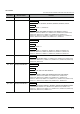
REVISIONS The manual number is written at the bottom left of the back cover. Print date Manual number Jul., 2008 SH(NA)-080788ENG-A Jan., 2009 SH(NA)-080788ENG-B Revision First edition Model Addition Q00UJ, Q00U, Q01U, Q10UDH, Q10UDEH, Q20UDH, Q20UDEH, FXCPU Addition MANUALS, Section 1.1, Section 3.6 Correction GENERIC TERMS AND ABBREVIATIONS IN THIS MANUAL, Section 1, Section 2.2, Section 3, Section 3.2.1, Section 3.2.2, Section 3.2.3, Section 3.2.5, Section 3.2.6, Section 3.2.7, Section 3.3.
Print date Manual number Sep., 2010 SH(NA)-080788ENG-G Jan., 2011 SH(NA)-080788ENG-H Jul., 2011 SH(NA)-080788ENG-I Revision Correction GENERIC TERMS AND ABBREVIATIONS IN THIS MANUAL, Section 3.2.3, Section 3.2.6, Section 3.3.1, Section 3.3.2, Section 3.5, Section 3.6 Correction MANUALS, Section 2.1, Section 3.2.1, Section 3.2.2, Section 3.2.3, Section 3.2.4, Section 3.2.5, Section 3.2.6, Section 3.2.7, Section 3.3.1, Section 3.3.2, Section 3.4.1, Section 3.4.2, Section 3.5, Section 3.6, Section 3.7.
INTRODUCTION Thank you for purchasing the Mitsubishi integrated FA software, MELSOFT series. Before using the product, thoroughly read this manual to develop full familiarity with the functions and performance to ensure correct use. CONTENTS SAFETY PRECAUTIONS ...................................................................................................................... A - 1 CONDITIONS OF USE FOR THE PRODUCT ......................................................................................
4 3.5 Diagnosing the programmable controller 3 - 38 3.6 Reading a Project from programmable controller 3 - 39 3.7 Printing 3 - 41 Setting the printer....................................................................................................................... 3 - 41 3.7.2 Previewing a program ................................................................................................................ 3 - 42 3.7.3 Printing a program....................................................
5.2.5 Preparing (creating) the program configuration............................................................................5 - 5 5.2.6 Setting labels ................................................................................................................................ 5 - 8 5.2.7 Creating a program....................................................................................................................... 5 - 9 5.2.8 Compiling a program .......................................
■ MANUALS Related manuals are separately issued according to the purpose of their functions in GX Works2. ● Related manuals The manuals related to this product are shown below. Refer to the following tables when ordering required manuals.
3) Operation of iQ Works Manual name Manual number (Manual code) iQ Works Beginner's Manual Explains fundamental operation methods such as managing the system using MELSOFT Navigator and using system labels for users inexperienced with GX Works2. (Sold separately) SH-080902ENG (13JZ44) The Operating Manuals are included on the CD-ROM of the software package in a PDF file format. Manuals in printed form are sold separately for single purchase.
● Purpose of this manual This manual explains the operation for creating sequence programs in Structured project, one of the functions supported with GX Works2. Manuals for reference are listed in the following table according to their purpose. For information such as the contents and manual number of each manual, refer to the list of 'Related manuals'.
2) Operation of GX Works2 For details of instructions used in each programming language, refer to the section 3 on the next page.
3) Details of instructions in each programming language (for QCPU (Q mode)/LCPU) Purpose MELSECQ/L/F Structured Programming Manual Fundamentals MELSEC-Q/L Structured Programming Manual MELSECQ/L Programming Manual MELSEC-Q/L/QnA Programming Manual Common Special Application Common PID Control Instructions Instructions Functions Instructions Instructions Learning details of programmable controller CPU All languages error codes, special relays, and special registers Details Learning the types and de
4) Details of instructions in each programming language (for FXCPU) Purpose MELSECQ/L/F Structured FXCPU Structured Programming Manual Programming Manual FX0, FX0S, FX0N, FX1, FXU, FX2C FX1S, FX1N, FX2N, FX1NC, FX2NC FX3G, FX3U, FX3UC Using ladder language Learning the types and details of basic/application instructions, descriptions of devices and parameters Details Details Details Using SFC language Learning details of specifications, functions, and instructions of SFC Details Details Deta
● How to read this manual Chapter heading Index on the right of the page number clarifies the chapter of currently opened page. Section title Clarifies the section of currently opened page. Reference location leads to the reference location and reference manuals. Section title Clarifies the section of currently opened page. * Since the above page was created for explanation purpose, it differs from the actual page.
This manual also uses the following columns: This explains notes for requiring attention or useful functions relating to the information given on the same page. Restrictions This explains restrictions relating to the information given on the same page. ● Symbols used in this manual The following shows the symbols used in this manual with descriptions and examples. No.
■ GENERIC TERMS AND ABBREVIATIONS IN THIS MANUAL This manual uses the generic terms and abbreviations listed in the following table to discuss the software packages and programmable controller CPUs. Corresponding module model names are also listed if needed.
OVERVIEW This manual explains the procedures to actually create a program (Structured Project) using GX Works2 and operate the programmable controller using the created program. If this is your first time creating a Structured Project using GX Works2, you are recommended to read this manual first, and then use GX Works2.
GX Works2 1 OVERVIEW 1.1 ■ Simple Project and Structured Project Simple Project In a Simple Project, you can create sequence programs using instructions for the Mitsubishi programmable controller CPU. The Simple Project offers the same operability for program creation as the conventional GX Developer. You can create sequence programs using the following programming languages: ● Graphic languages • Ladder Use this graphic language to describe programs as ladders consisting of contacts, coils, etc.
1.1 Simple Project and Structured Project 1 Restrictions The FXCPU does not support the ST language in Simple Project, and does not support the ladder language and SFC language in Structured Project. 2 CREATED PROGRAM AND SYSTEM CONFIGURATION • ST (Structured Text) This text language allows you to describe controls by syntax including alternative sequences offered by conditional sentences and repetition offered by repetition sentences in the same way as high-level languages such as the C language.
GX Works2 1 OVERVIEW 1.2 Program Creation Procedure The figure below shows how to create a program with a Structured Project and execute it in a programmable controller CPU. 1. Opening a project Procedure 3.2.1 Create a new Structured Project. Or open an existing Structured Project. 3.2.3 2. Setting parameters Procedure Set the parameters. 3. Reference 3.2.4 Creating the program configuration Procedure Reference Create Program File. -- Create Task in Program File. -- Create POU.
1.2 Program Creation Procedure Conversion Procedure 3.2.7 Connecting the programmable controller CPU Procedure Connect the personal computer to the programmable controller CPU. Set the connection destination. 8. Reference 3.3.1 3 Writing to the programmable controller Procedure Write the parameters to the programmable controller CPU. Reference 4 3.3.2 CREATING PROGRAM IN ST LANGUAGE Write the program to the programmable controller CPU. 9.
GX Works2 1 OVERVIEW MEMO 1-6
CREATED PROGRAM AND SYSTEM CONFIGURATION 3 CREATING PROGRAM IN STRUCTURED LADDER/ FBD LANGUAGE This chapter explains the system configuration and gives an overview of the program created by using this manual. 2 CREATED PROGRAM AND SYSTEM CONFIGURATION 2 OVERVIEW 1 4 CREATING PROGRAM IN ST LANGUAGE 2.1 System Configuration . . . . . . . . . . . . . . . . . . . . . . . . . . . . . . . . . 2-2 2.2 Overview of Program Creation. . . . . . . . . . . . . . . . . . . . . . . . . .
GX Works2 2 CREATED PROGRAM AND SYSTEM CONFIGURATION 2.1 System Configuration This manual uses GX Works2 and the Q Series programmable controller for explanation. Programmable controller (QCPU) GX Works2 USB cable 2.2 Overview of Program Creation This manual explains the following program creation procedures using the simple example program shown in the table below.
2.2 Overview of Program Creation 1 Table 2.1 Overview of created program Number of program blocks Operation overview Reference OVERVIEW Program language FBD 1 Chapter 3 CREATED PROGRAM AND SYSTEM CONFIGURATION 2 ST 1 Chapter 4 CREATING PROGRAM IN STRUCTURED LADDER/ FBD LANGUAGE 3 SFC Refer to the following manual. GX Works2 Beginner's Manual (Simple Project) 5 CREATING TWO OR MORE PROGRAM BLOCKS Ladder Refer to the following manual.
GX Works2 2 CREATED PROGRAM AND SYSTEM CONFIGURATION MEMO 2-4
CREATING PROGRAM IN STRUCTURED LADDER/ FBD LANGUAGE CREATED PROGRAM AND SYSTEM CONFIGURATION 2 This chapter explains how to create a program in the Structured Ladder/FBD language with a Structured Project using a simple Structured Ladder program.
GX Works2 3 CREATING PROGRAM IN STRUCTURED LADDER/FBD LANGUAGE 3.1 Created Program This section explains the operations of the program to be created and ladder programs. 3.1.1 Operations of program ● When X0 turns ON, the programmable controller turns ON Y10, and then turns OFF Y10 1 second later. ● When X1 turns ON, the programmable controller transfers K10 to D0 (which is defined with the LABEL "VAR1").
3.2 Creating a Project 1 Creating a Project OVERVIEW 3.2 Create a project using Structured Ladder programs. Refer to Section 3.2.8 for creating an FBD program. 2 Starting GX Works2 1. CREATED PROGRAM AND SYSTEM CONFIGURATION 3.2.1 Select the software package menu to be started. CREATING PROGRAM IN STRUCTURED LADDER/ FBD LANGUAGE 3 2. CREATING PROGRAM IN ST LANGUAGE 4 The selected software package is started.
GX Works2 3 CREATING PROGRAM IN STRUCTURED LADDER/FBD LANGUAGE 3.2.2 Screen configuration in GX Works2 The GX Works2 screen has the following configuration. Select "View" or "Hide" in the [View] menu for each of the Toolbar, Status bar, Navigation Window, Function Block Selection window and Output window.
3.2 Creating a Project At first, create a project. Perform either procedure below to display the New Project screen. • Select [Project] • Click 2 [New]. CREATED PROGRAM AND SYSTEM CONFIGURATION 1. OVERVIEW 1 Creating a new project (New). 2. Select the "Project Type", "PLC Series", "PLC Type" and "Language" from the list boxes for the new project to be created. After the setting, click the CREATING PROGRAM IN STRUCTURED LADDER/ FBD LANGUAGE 3 4 button. Settings 3.
GX Works2 3 CREATING PROGRAM IN STRUCTURED LADDER/FBD LANGUAGE Opening an existing project Refer to the following manual for the details on the existing project opening procedure: GX Works2 Version 1 Operating Manual (Common) 1. Perform either operation below. • Select [Project] • Click 2. [Open]. (Open). The Open Project screen appears. Select an existing project to be opened in the "Workspace Location" and "Workspace/ Project List".
3.2 Creating a Project Set parameters. Double-click "Parameter" "PLC Parameter" on the Project view to display the Q Parameter Setting screen. 2 CREATED PROGRAM AND SYSTEM CONFIGURATION 1. OVERVIEW 1 Setting parameters Double-click it. CREATING PROGRAM IN STRUCTURED LADDER/ FBD LANGUAGE 3 Click the [End] button after finishing the setting. 4 Click the button to determine the settings and close the screen. The parameters remain unchanged from the initial setting in the example in this manual.
GX Works2 3 CREATING PROGRAM IN STRUCTURED LADDER/FBD LANGUAGE 3.2.5 Setting labels Set Global Labels. 1. Double-click "Global Label" "Global1" on the Project view to display the Global Label Setting screen. 2. Select the "Class" from the list box on the Global Label Setting screen. Settings • Class: VAR_GLOBAL 3. Directly input the "Label Name" on the Global Label Setting screen.
3.2 Creating a Project 1 OVERVIEW Directly input the "Date Type" on the Global Label Setting screen. Settings • Date Type: Word [Signed] CREATED PROGRAM AND SYSTEM CONFIGURATION You can click 2 to display the Type Selection screen, and then select the Types on this screen.
GX Works2 3 CREATING PROGRAM IN STRUCTURED LADDER/FBD LANGUAGE 6. Set the "Constant", "Comment" and "Remark" on the Global Label Setting screen. "Relation with System Label", "System Label Name" and "Attribute" are not used in examples shown in this manual. Settings • Constant • Comment • Remark : When the label class is "VAR_GLOBAL", you cannot set or change the initial value.
3.2 Creating a Project 1 Creating a program Create the Structured ladder/FBD program shown in Section 3.1.2. Double-click "POU" "Program" "POU_01" "Program" on the Project view to display the POU_01 [PRG] Program [Structured Ladder/FBD] screen. 2 CREATED PROGRAM AND SYSTEM CONFIGURATION 1. OVERVIEW 3.2.6 Double-click it. Drag "Function" "LDP" from the Function Block Selection window, and drop it on the POU_01 [PRG] Program [Structured Ladder/ FBD] screen to position it there. Position "LDP".
GX Works2 3 CREATING PROGRAM IN STRUCTURED LADDER/FBD LANGUAGE Start Point 3. End Point Click (Interconnect Mode) on the Structured Ladder/FBD toolbar to specify the Interconnect mode. Click the start point and end point in this order to draw a grid line as shown left. (GX Works2 is using the Auto Connect function described in "Point".) Connection with grid line Connect ladder symbols such as contacts, coils, Function and Function block with grid lines.
3.2 Creating a Project Set the function "LDP". Click the input variable "?" of "s", and set the input variable. Settings • s: X0 Input Variable 2 Referring to the data type of input/output labels in a Function or Function block Double-click a positioned function or function block to display the Function/FB Label Setting screen where you can refer to the data type of labels.
GX Works2 3 CREATING PROGRAM IN STRUCTURED LADDER/FBD LANGUAGE 7. Click (Close contact) on the Structured Ladder/FBD toolbar, and then move the cursor to a desired position to display a close contact there. Click the close contact to connect it with a function of the LDP and enable setting of a variable. Settings • Variable: TS0*1 *1: "TS0" indicates a contact of the timer T0. 8. Draw a grid line on the left figure (position 1) using the procedure described in the step 3.
3.2 Creating a Project described in the step 3. • After drawing a grid line, click (Select Mode) on the Structured Ladder/FBD toolbar to specify the Select mode. 12.Select a ladder block, and click (New Ladder Block After) on the Structured Ladder/ FBD toolbar to add a ladder block. Create a one Structured Ladder program in one ladder block. (Open Contact) on the Structured Ladder/FBD toolbar, and then move the cursor to a desired position to display an open contact there.
GX Works2 3 CREATING PROGRAM IN STRUCTURED LADDER/FBD LANGUAGE Selecting a label from the Label Registration/Selection screen You can input a label also by selecting it from the Label Registration/Selection screen. Perform the following procedure to display the Label Registration/Selection screen. ● Select "Edit" ● Click "List Operands". (List Operands).
3.2 Creating a Project Click the open contact to connect it with the left bus line and enable setting of a variable. Settings • Variable: X2 17.Select "Function" "MOVP" on the Function Block Selection window, drag it, and drop it in a desired position to position "MOVP" there. 1) Input variable "s" Output variable "d" Draw a grid line on the left figure (position 1) using the procedure described in the step 3. Click "?" of "s" and "d", and set the input and output variables.
GX Works2 3 CREATING PROGRAM IN STRUCTURED LADDER/FBD LANGUAGE Copying a ladder block by drag & drop When there is a similar ladder block, you can create a new ladder block efficiently by copying the existing similar ladder block and editing necessary portions. Drag an existing ladder block, and drop it while pressing the Drag it, and drop it while pressing key to copy the existing ladder block. . Change "X1" to "X2" in this example. Change "10" to "20" in this example.
3.2 Creating a Project Table 3.1 Compiling type and target program Target program to be compiled Build Converts non-compiled program blocks among program blocks registered in the task into sequence program. (Does not compile already compiled program blocks.) Rebuild All Converts all program blocks registered in the task into sequence program. (Compiles already compiled program blocks also.) 1. Select [Compile] "Rebuild All". You can click All".
GX Works2 3 CREATING PROGRAM IN STRUCTURED LADDER/FBD LANGUAGE 3.2.8 Creating an FBD program Create an FBD program using the same procedure for Structured Ladder programs without using left power rail on the left for Structured Ladder. Display or hide left power rail by selecting [Edit] on the menu bar, selecting [Ladder Symbol], and clicking [Left Power Rail]. Or hide Left Power Rail by clicking Refer to 3.1.2 for an FBD program. on the Structured Ladder/FBD tool bar.
3.3 Writing a Project to the programmable controller 1 Connecting the personal computer to the programmable controller Connect the personal computer and a programmable controller with a cable, and set the connection channel. ■ Connecting the personal computer to the programmable controller 3 Make sure to turn OFF the power of all units before connecting the personal computer to the programmable controller CPU.
GX Works2 3 CREATING PROGRAM IN STRUCTURED LADDER/FBD LANGUAGE 3. Double-click (Serial USB) in "PC side I/F" to display the PC side I/F Serial setting screen. 4. Set the PC side I/F. Double-click it. After the setting, click the button to complete the setting and close the screen. Settings • Select "USB". 5. Click (PLC Module) in "PLC side I/F" to select the interface to be used. Click it. (To the next page) 3 - 22 3.3.
3.3 Writing a Project to the programmable controller 6. 2 CREATED PROGRAM AND SYSTEM CONFIGURATION Click it. Click the button to execute a communication test with the programmable controller through the specified connection channel. OVERVIEW 1 CREATING PROGRAM IN STRUCTURED LADDER/ FBD LANGUAGE 3 Click the button to close the screen. If communication with the programmable controller has failed, the screen below appears. Check the connection destination, connection cable, etc. 8.
GX Works2 3 CREATING PROGRAM IN STRUCTURED LADDER/FBD LANGUAGE ● You can set two or more connection destinations and change them over if there are two or more connection destinations. 1. Select "Connection1" in the Current Connection on the Connection Destination view, right-click it, and then select the menu item "Add New Data". The Add New Data screen will appear. 2. Set "Data Name", and uncheck "Set as Default Connection".
3.3 Writing a Project to the programmable controller 1. Select "Connection2" in the All Connections on the Connection Destination view, right-click it, and then select the menu item "Set as Default Connection". 2 CREATED PROGRAM AND SYSTEM CONFIGURATION ● For selecting the newly created connection destination, check "Set as Default Connection " while creating the data, or set the newly created connection destination as the default connection destination as described below.
GX Works2 3 CREATING PROGRAM IN STRUCTURED LADDER/FBD LANGUAGE 3.3.2 Writing a project to the programmable controller Write the project data to the programmable controller CPU set as the connection destination in Section 3.3.1. 1. Select "Online" "Write to PLC" to display the Online Data Operation screen. You can click (Write to PLC) to display the Online Data Operation screen. 2. Setting of the target module Set the "Target module" and "Target project" on the Online Data Operation screen.
3.3 Writing a Project to the programmable controller 1 3. The left screen is displayed. Click the button to write the project (program). 2 CREATED PROGRAM AND SYSTEM CONFIGURATION In the case of FXCPU • The symbolic information is displayed only in the FX3U and FX3UC Series version 3.00 or later. • In the case of structured project, data can be read from the FXCPU only in the FX3U and FX3UC Series version 3.00 or later.
GX Works2 3 CREATING PROGRAM IN STRUCTURED LADDER/FBD LANGUAGE 5. 3 - 28 3.3.2 Writing a project to the programmable controller Click the button to close the Online Data Operation screen.
3.4 Monitoring Operations 1 OVERVIEW Monitoring Operations Execute "Monitor" to check the operations. In some monitor screen display examples, colors are changed for the convenience of printing. GX Works2 has the function to simulate programmable controller operations in the offline mode. Refer to the following manual for the simulation function: GX Works2 Version 1 Operating Manual (Common) Click "Project" in the view selection area on the Navigation window to display the Project view.
GX Works2 3 CREATING PROGRAM IN STRUCTURED LADDER/FBD LANGUAGE You can switch the programmable controller status between "RUN" and "STOP" using remote operation as follows. The Settings of the remote operation may vary depending on the programmable controller used. Refer to the following manual for the details on the remote operation: GX Works2 Version 1 Operating Manual (Common) Select [Online] [Remote Operation] to display the Remote Operation screen.
3.4 Monitoring Operations 1 OVERVIEW Monitor status GX Works2 displays the Monitor status while it is executing the work window monitor. The Monitor status disappears when GX Works2 stops all types of monitoring. The Monitor status indicates the programmable controller CPU, simulator scan time, RUN/STOP status, etc. 2 Scan status CREATED PROGRAM AND SYSTEM CONFIGURATION Select the Local Device monitor USER status ERR.
GX Works2 3 CREATING PROGRAM IN STRUCTURED LADDER/FBD LANGUAGE Test operation ● Forcing a contact ON/OFF Double-click a monitored device or label while pressing the key to force a device in the programmable controller ON/OFF. ● Changing the current value of a word device Double-click a monitored word device to display the Modify Value screen where you can change the current value. Input the numeric value to be set, and click the button to change the current value to the input numeric value. 3 - 32 3.4.
3.4 Monitoring Operations You can turn ON inputs X0, X1 and X2 using the test operation above. • When X0 turns ON, the programmable controller turns ON Y10, and then turns OFF Y10 1 second later. X0 turns ON. Y10 remains ON for 1 second. 2 CREATED PROGRAM AND SYSTEM CONFIGURATION Turn ON inputs X0, X1 and X2 in the programmable controller, and check the following operations.
GX Works2 3 CREATING PROGRAM IN STRUCTURED LADDER/FBD LANGUAGE 3.4.2 Batch monitoring of device values 1. Select [Online] [Monitor] [Device/Buffer Memory Batch] to display the Device/Buffer Memory Batch Monitor screen. Or click (Device/Buffer Memory Batch Monitor) to display the Device/Buffer Memory Batch Monitor screen. Setting 2. Set a device to be monitored. Select D0 in this example. Setting of "Device" • Device : Select "Device Name". • Device Name : D0 3.
3.4 Monitoring Operations ● You can save the contents set on the Display Format screen. When the monitoring screen is opened again, the contents set previously on the Display Format screen will not be displayed. (The default setting will be displayed.) To display the previous setting, you can save the setting to a file, and read the file. To save the setting, click Save Display Format on the Device/Buffer Memory Batch Monitor screen.
GX Works2 3 CREATING PROGRAM IN STRUCTURED LADDER/FBD LANGUAGE Click it. 8. Click on the screen to close the Device/ Buffer Memory Batch Monitor screen. 9. Set the programmable controller CPU to STOP. Set the RUN/STOP switch on the programmable controller CPU to "STOP". You can switch the programmable controller status between "RUN" and "STOP" using remote operation. For the remote operation, refer to the following. "Point" in the 3.4.
3.4 Monitoring Operations Click the button to display the Modify Value screen. Or click (Modify Value) to display the Modify Value screen. Click it. 2 CREATED PROGRAM AND SYSTEM CONFIGURATION 2. OVERVIEW 1 3. Change the current value. 4 CREATING PROGRAM IN ST LANGUAGE For the change procedure, refer to the following. "Point" in the 3.4.1 CREATING PROGRAM IN STRUCTURED LADDER/ FBD LANGUAGE 3 CREATING TWO OR MORE PROGRAM BLOCKS 5 3.4.
GX Works2 3 CREATING PROGRAM IN STRUCTURED LADDER/FBD LANGUAGE 3.5 Diagnosing the programmable controller You can check the programmable controller RUN/STOP status and error status. Refer to the following manual for the details on Network Diagnostics, Ethernet Diagnostics and CC-Link IE Control Diagnostics. GX Works2 Version 1 Operating Manual (Common) 1. Select [Diagnostics] [PLC Diagnostics] to display the PLC Diagnostics screen. 1) 2) 3) 5) 4) 7) 8) 9) 10) 11) 7) 9) 13) 14) 12) 15) 16) No.
3.6 Reading a Project from programmable controller 1 Select [Online] [Read from PLC] to display the Online Data Operation screen. You can click (Read from PLC) to display the Online Data Operation screen. 2. After the setting, click the button to read the project (program) from the programmable controller. 3 4 CREATING PROGRAM IN ST LANGUAGE Setting of the target module Set the "Target module" and "Target project" on the Online Data Operation screen. 2 CREATED PROGRAM AND SYSTEM CONFIGURATION 1.
GX Works2 3 CREATING PROGRAM IN STRUCTURED LADDER/FBD LANGUAGE If a program or parameters already exist in the GX Works2, the following screen appears. Click the or button to overwrite the existing program or parameters. When you click the button, GX Works2 overwrite the existing program or parameters without displaying the overwrites confirmation screen for other data. When symbolic information already exists When parameters already exist 3. The left screen is displayed during reading.
3.7 Printing 1 OVERVIEW Printing You can print programs and parameters created using GX Works2 in a printer. The print function consists of Batch print and print. This section explains print. For details of printing, refer to the following manual. GX Works2 Version 1 Operating Manual (Common) Setting the printer Select [Project] [Printer Setup] to display the Printer Setup screen. 3 CREATING PROGRAM IN STRUCTURED LADDER/ FBD LANGUAGE 1.
GX Works2 3 CREATING PROGRAM IN STRUCTURED LADDER/FBD LANGUAGE 3.7.2 Previewing a program You can display a program in the image of printing. 1. Click "Project" in the view selection area on the Navigation window to display the Project view. 2. Double-click "POU" "Program" "POU_01" "Program" on the Project view to display the POU_01 [PRG] Program [Structured Ladder/FBD] screen. Click it. Double-click it. (To the next page) 3 - 42 3.7.
3.7 Printing 3. Select [Project] [Print Window Preview] to display the Print Window Preview screen. OVERVIEW 1 CREATED PROGRAM AND SYSTEM CONFIGURATION 2 CREATING PROGRAM IN STRUCTURED LADDER/ FBD LANGUAGE 3 4 CREATING PROGRAM IN ST LANGUAGE After checking the contents, click the button to print the program. Click the button to close the Print Window Preview screen. Click button to print the program. 5 CREATING TWO OR MORE PROGRAM BLOCKS 4. 3.7.
GX Works2 3 CREATING PROGRAM IN STRUCTURED LADDER/FBD LANGUAGE 3.7.3 Printing a program 1. Display a program. For the display procedure, refer to the following. 3.7.2 Previewing a program Click it. 3 - 44 3.7.3 Printing a program 2. Select [Project] [Print Window] to display the Print Window screen. 3. Click the button to start printing.
3.7 Printing You can display PLC Parameter in the image of printing. 1. Display PLC parameters. Double-click "Parameter" "PLC Parameter" on the Project view to display the Q Parameter Setting screen. Double-click it. OVERVIEW 1 Previewing a PLC Parameter 2 CREATED PROGRAM AND SYSTEM CONFIGURATION 3.7.4 2. Click the CREATING PROGRAM IN STRUCTURED LADDER/ FBD LANGUAGE 3 button. CREATING PROGRAM IN ST LANGUAGE 4 Click it. 3.
GX Works2 3 CREATING PROGRAM IN STRUCTURED LADDER/FBD LANGUAGE 3.7.5 Printing a PLC Parameter 1. Display a PLC Parameter. For the display procedure, refer to the following. 3.7.4 Previewing a PLC Parameter 2. Click the 3. Click the button. Click it. Click it. 3 - 46 3.7.5 Printing a PLC Parameter button to start printing.
3.8 Saving a Project 1 You can save a project. When saving a newly created project, use the menu item [Save as]. Select [Project] Save As screen. [Save As] to display the 2 CREATED PROGRAM AND SYSTEM CONFIGURATION 1. OVERVIEW Saving a Project After the setting, click the button to save the project (program). Refer to the following manual for the details: GX Works2 Version 1 Operating Manual (Common) Settings • Save Location : Specify the save destination folder.
GX Works2 3 CREATING PROGRAM IN STRUCTURED LADDER/FBD LANGUAGE 3.9 Exiting GX Works2 End the project. 1. Select [Project] 2. Click the If you have not saved the project, the following message appears. 3 - 48 Click the button to save the project. Click the button to exit GX Works2 without saving the project. 3.7.5 Printing a PLC Parameter [Exit (Q)]. button to exit GX Works2.
CREATING PROGRAM IN ST LANGUAGE This chapter explains how to create a program in the ST language with a Structured Project using a simple ST program. Refer to the following manuals for the details on structured programs including programming languages, labels, data types and functions (instructions): MELSEC-Q/L/F Structured Programming Manual (Fundamentals) Structured Programming Manual of the programmable controller CPU 3 4 CREATING PROGRAM IN ST LANGUAGE Created Program . . . . . . . . . . . . . . . .
GX Works2 4 CREATING PROGRAM IN ST LANGUAGE 4.1 Created Program This section explains the operations of the program to be created and ST programs. 4.1.1 Operations of program ● When X0 turns ON, the programmable controller turns ON Y10, and then turns OFF Y10 1 second later. ● When X1 turns ON, the programmable controller transfers K10 to D0 (which is defined with the LABEL "VAR1"). ● When X2 turns ON, the programmable controller transfers K20 to D0 (which is defined with the LABEL "VAR1"). 4.1.
4.2 Creating a Project 1 Creating a Project OVERVIEW 4.2 Create a project using ST program. Starting GX Works2 2 CREATED PROGRAM AND SYSTEM CONFIGURATION 4.2.1 Refer to the following section for the GX Works2 startup procedure: 3.2.1 Starting GX Works2 3 Screen configuration in GX Works2 CREATING PROGRAM IN STRUCTURED LADDER/ FBD LANGUAGE 4.2.2 Refer to the following section for the GX Works2 screen configuration: 3.2.
GX Works2 4 CREATING PROGRAM IN ST LANGUAGE 4.2.6 Creating a program Create the ST program shown in Section 4.1.2. 1. Double-click "POU" "Program" "POU_01" "Program" on the Project view to display the POU_01 [PRG] Program [ST] screen. 2. Input "Y10:=(LDP(TRUE*1, X0) OR Y10) AND Double-click it. NOT (TS0*2);" directly, and click the key. You can use the Function Block Selection window for the input. Settings • Y10:= (LDP(TRUE*1, X0) OR Y10) AND NOT (TS0*2); *1: "TRUE" indicates the ON status.
4.2 Creating a Project 1 OVERVIEW ● Display colors GX Works2 displays syntax, operators, comments, constants, string constants, devices and labels using the following colors (in the initial setting).
GX Works2 4 CREATING PROGRAM IN ST LANGUAGE Selecting a label from the Label Registration/Selection screen You can input a label also by selecting it from the Label Registration/Selection screen. Perform the following procedure to display the Label Registration/Selection screen. ● Select "Edit" ● Click "List Operands". (List Operands).
4.3 Writing a Project to the programmable controller 1 OVERVIEW Writing a Project to the programmable controller Refer to the following section for the procedure to write a project to the programmable controller CPU. 3.3 Writing a Project to the programmable controller 2 CREATED PROGRAM AND SYSTEM CONFIGURATION Monitoring Operations Execute "Monitor" to check the operations. Note that some screen shot colors have been changed for printing convenience.
GX Works2 4 CREATING PROGRAM IN ST LANGUAGE You can switch the programmable controller status between "RUN" and "STOP" using remote operation as follows. The Settings of the remote operation may vary depending on the programmable controller used. Refer to the following manual for the details on the remote operation: GX Works2 Version 1 Operating Manual (Common) Select [Online] [Remote Operation] to display the Remote Operation screen.
4.4 Monitoring Operations 1 OVERVIEW Monitor status GX Works2 displays the Monitor status while it is executing the work window monitor. The Monitor status disappears when GX Works2 stops all types of monitoring. The Monitor status indicates the programmable controller CPU, simulator scan time, RUN/STOP status, etc. Scan status 2 CREATED PROGRAM AND SYSTEM CONFIGURATION Select the Local Device monitor USER status ERR.
GX Works2 4 CREATING PROGRAM IN ST LANGUAGE 5. Turn ON inputs X0, X1 and X2 in the programmable controller, and check the following operations. You can turn ON inputs X0, X1 and X2 using the test operation above. • When X0 turns ON, the programmable controller turns ON Y10, and then turns OFF Y10 1 second later. Y10 remains ON for 1 second. X0 turns ON. • When X1 turns ON, the programmable controller transfers K10 to VAR1 (device: D0). X1 turns ON. VAR1 becomes "10".
4.5 Diagnosing the programmable controller 1 Diagnosing the programmable controller OVERVIEW 4.5 You can check the programmable controller RUN/STOP status and error status. Refer to the following section for the diagnosis procedure: 3.5 Diagnosing the programmable controller Reading a Project from programmable controller CREATED PROGRAM AND SYSTEM CONFIGURATION 4.6 2 Refer to the following section for the procedure to read a project from the programmable controller: 3.
GX Works2 4 CREATING PROGRAM IN ST LANGUAGE MEMO 4 - 12 4.4.
This chapter explains how to create a Structured Project in which two or more program blocks are made into one program using a simple example. Refer to the following manuals for the details on structured programs including programming languages, labels, data types and functions (instructions): MELSEC-Q/L/F Structured Programming Manual (Fundamentals) Structured Programming Manual of the programmable controller CPU 3 4 CREATING PROGRAM IN ST LANGUAGE Created Program . . . . . . . . . . . . . . . . . . . .
GX Works2 5 CREATING TWO OR MORE PROGRAM BLOCKS 5.1 Created Program This section explains how to create a program for controlling a tea server system which consists of a tea pouring operation, water refilling operation and warning indicating operation. This section also explains a program which works as one Structured Project, and the program operations. 5.1.
5.1 Created Program 5.1.2 1 Created program ■ Program block for the tea pouring operation ■ Program block for the water refilling operation OVERVIEW Create the following program blocks. CREATED PROGRAM AND SYSTEM CONFIGURATION 2 CREATING PROGRAM IN STRUCTURED LADDER/ FBD LANGUAGE 3 Program block for the warning indicating operation 5 CREATING TWO OR MORE PROGRAM BLOCKS ■ CREATING PROGRAM IN ST LANGUAGE 4 5.1.
GX Works2 5 CREATING TWO OR MORE PROGRAM BLOCKS 5.2 Creating a Project Create projects for the tea pouring operation, water refilling operation and warning indicating operation using Structured Ladder program. 5.2.1 Starting GX Works2 Refer to the following section for the GX Works2 startup procedure: 3.2.1 Starting GX Works2 5.2.2 Screen configuration in GX Works2 Refer to the following section for the GX Works2 screen configuration: 3.2.2 Screen configuration in GX Works2 5.2.
5.2 Creating a Project Create a POU (three program blocks) for Structured Ladder/FBD program, and register the three program blocks created in the POU to a task. When you create a new project, GX Works2 automatically creates the Program File, Task and POU shown in the table below. Item Name Program Setting (No Execution Type) MAIN Task Task_01 The program block "POU_01" is registered in "Task_01". POU POU_01 2 CREATED PROGRAM AND SYSTEM CONFIGURATION Table 5.
GX Works2 5 CREATING TWO OR MORE PROGRAM BLOCKS 3. Select "POU" "Program" on the Project view, right-click "Program", and then select the menu item "Add New Data". The "New Data" screen appears. When creating a new project, GX Works2 automatically creates "POU_01 [PRG]" under "POU_Pool". Because the language (Structured Ladder/FBD) used in this chapter is same as the language adopted in "POU_01 [PRG]", you can use "POU_01 [PRG]" by changing its data name instead of deleting it. 4.
5.2 Creating a Project 1 "No Execution *1 Type" "MAIN" Task_01 on the Project view, right-click the Task_01, and then select the menu item "Open Task Setting". The Task Setting (task name*1) window appears. *1: The Task Name is "Task_01" for this example. OVERVIEW Select "Program Setting" 2 CREATED PROGRAM AND SYSTEM CONFIGURATION 5. CREATING PROGRAM IN STRUCTURED LADDER/ FBD LANGUAGE 3 6. CREATING PROGRAM IN ST LANGUAGE 4 Click the button to display the Program Selection screen. 5 7.
GX Works2 5 CREATING TWO OR MORE PROGRAM BLOCKS 5.2.6 Setting labels Refer to the following section for the global label setting procedures: Refer to the following "Setting global labels" for settings: 3.2.
5.2 Creating a Project 1 Creating a program Creating the program block for the tea pouring operation Create the program block for the tea pouring operation shown in Section 5.1.2. 1. Double-click "POU" "Program" "pouring" "Program" on the Project view to display the pouring [PRG] Program [Structured Ladder/ FBD] screen. Double-click it.
GX Works2 5 CREATING TWO OR MORE PROGRAM BLOCKS ■ Creating the program block for the water refilling operation Create the program block for the water refilling operation shown in Section 5.1.2. 1. Double-click "POU" "Program" "refilling" "Program" on the Project view to display the refilling [PRG] Program [Structured Ladder/ FBD] screen. 2. Create the program block for the water refilling operation shown in Section 5.1.2. Double-click it.
5.2 Creating a Project 1 Create the program block for the warning indicating operation shown in Section 5.1.2. 1. Double-click "POU" "Program" "indicating" "Program" on the Project view to display the indicating [PRG] Program [Structured Ladder/ FBD] screen. OVERVIEW Creating the program block for the warning indicating operation 2 CREATED PROGRAM AND SYSTEM CONFIGURATION ■ CREATING PROGRAM IN STRUCTURED LADDER/ FBD LANGUAGE 3 Double-click it.
GX Works2 5 CREATING TWO OR MORE PROGRAM BLOCKS 5.3 Writing a Project to the programmable controller Refer to the following section for the procedure to write a project to the programmable controller CPU. 3.3 Writing a Project to the programmable controller 5.4 Monitoring Operations Execute monitoring, and check the operations. Note that some screen shot colors have been changed for printing convenience. GX Works2 is able to simulate programmable controller operations in offline mode.
5.4 Monitoring Operations You can also click (Start Monitoring), to switch individual screens to the monitoring status. 4. Set the programmable controller CPU to RUN. Set the RUN/STOP switch on the programmable controller CPU to "RUN". You can also switch the programmable controller status between "RUN" and "STOP" using remote operation. Refer to the next page for remote operation.
GX Works2 5 CREATING TWO OR MORE PROGRAM BLOCKS You can switch the programmable controller status between "RUN" and "STOP" using remote operation as follows. The Settings of the remote operation may vary depending on the programmable controller used. Refer to the following manual for the details of the remote operation: GX Works2 Version 1 Operating Manual (Common) Select [Online] [Remote Operation] to display the Remote Operation screen.
5.4 Monitoring Operations 1 OVERVIEW Monitor status GX Works2 displays the Monitor status while it is executing the work window monitor. The Monitor status disappears when GX Works2 stops all types of monitoring. The Monitor status indicates the programmable controller CPU, simulator scan time, RUN/STOP status, etc. 2 Scan status CREATED PROGRAM AND SYSTEM CONFIGURATION Select the Local Device monitor USER status ERR.
GX Works2 5 CREATING TWO OR MORE PROGRAM BLOCKS Test operation ● Forcing a contact ON/OFF Double-click a monitored device or label while pressing the key to force a device in the programmable controller ON/OFF. ● Changing the current value of a word device Double-click a monitored word device to display the Modify Value screen where you can change the current value. Input the numeric value to be set, and click the button to change the current value to the input numeric value. 5 - 16 5.4.
5.4 Monitoring Operations Turn ON inputs X0, X1 and X2 in the programmable controller, and check the following operations. You can turn ON inputs X0, X1 and X2 using the test operation above. X1 (Tea_pouring_button) turns ON The programmable controller turns ON Y10 (Tea_pouring_output). while X0 (Cup_detection) is ON. 3 • When X3 turns ON, the programmable controller turns ON Y11. The programmable controller turns ON Y11 (Water_refill_output).
GX Works2 5 CREATING TWO OR MORE PROGRAM BLOCKS 6. Select [Online] [Monitor] [Stop Monitoring (All Windows)] to reset the monitor status on all monitored screens. You can also click Stop Monitoring (All Windows) to reset each monitored screens. 7. Set the programmable controller CPU to STOP. Set the RUN/STOP switch on the programmable controller CPU to "STOP". You can switch the programmable controller status between "RUN" and "STOP" using remote operation. "Point" in the step4 5.4.
5.7 Printing 1 Printing OVERVIEW 5.7 For the Printing a project procedure, refer to the following. 3.7 Printing CREATED PROGRAM AND SYSTEM CONFIGURATION 2 CREATING PROGRAM IN STRUCTURED LADDER/ FBD LANGUAGE 3 4 Saving a Project CREATING PROGRAM IN ST LANGUAGE 5.8 Refer to the following section for the project saving procedure: 3.8 Saving a Project Exiting GX Works2 5 CREATING TWO OR MORE PROGRAM BLOCKS 5.9 Refer to the following section for the project ending procedure: 3.
Microsoft, Windows are registered trademarks of Microsoft Corporation in the United States and other countries. Ethernet is a registered trademark of Xerox Corporation in the United States. Other company names and product names used in this document are trademarks or registered trademarks of respective companies.