
User's Manual

2. DEVICE RANGE THAT CAN BE SET
2 - 7
1
PREPARATORY
PROCEDURES FOR
MONITORING
2
DEVICE RANGE
THAT CAN BE SET
3
ACCESS RANGE
FOR MONITORING
4
HOW TO MONITOR
REDUNTANT
SYSTEM
5
BUS CONNECTION
6
DIRECT
CONNECTION TO
CPU
7
COMPUTER LINK
CONNECTION
8
ETHERNET
CONNECTION
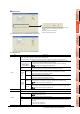
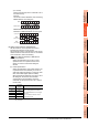
•(For 32 bits)
Monitor and write only b8 to b15 and b24 to 31 of
the buffer memory.
Example:
The monitor value is 00870043
H when monitoring
BM0=87654321
H as mask type 6.
BM0=65002100
H when writing input value
87654321H to BM0=00000000H as mask type 6.
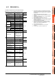
(5) Setting of the module No. (MELSEC-FX)
Set the module No. of the special function unit or
special function block to monitor or write.
The module No.0 to No.7 are assigned in order for the
nearest module or block from the main unit. For details
of the module No., refer to the following.
User's Manual (Hardware) of MELSEC-FX
(a) Direct specification
Specify the module No. (No.0 to No.7) of the
special function unit or special function block
directly, to monitor or write when setting the
devices.
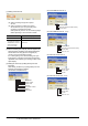
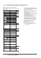
(b) Indirect specification
*1
Specify the module No. of the special function unit
or special function block indirectly, to monitor or
write when setting the devices, by using the 16-bit
GOT internal data register (GD10 to GD25).
When specifying the station No. from 100 to 115 on
GT Designer3, the value of GD10 to GD25
corresponding to the module No. will be the
module No. of the special function unit or special
function block.
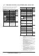
*1 The module No. cannot be specified indirectly for the multi-
drop connection.
Module No.
Compatible
device
Setting range
100 GD10
0 to 7
For the setting other than the above,
error (dedicated device is out of range)
will occur.
If a non-existent module No. is set, a
timeout error occurs.
101 GD11
::
114 GD24
115 GD25
H
BM0
87654321
00870043
H
Monitor value
H
BM0
87654321
00000000
H
Input value
BM0
65002100
H
(Before writing)
(After writing)