
User's Manual

1. PREPARATORY PROCEDURES FOR MONITORING
1.6 Checking for Normal Monitoring
1 - 47
1
PREPARATORY
PROCEDURES FOR
MONITORING
2
DEVICE RANGE
THAT CAN BE SET
3
ACCESS RANGE
FOR MONITORING
4
HOW TO MONITOR
REDUNTANT
SYSTEM
5
BUS CONNECTION
6
DIRECT
CONNECTION TO
CPU
7
COMPUTER LINK
CONNECTION
8
ETHERNET
CONNECTION
1.6.3 Confirming the communication state to each station (Station monitoring
function)
The station monitoring function detects the faults (communication timeout) of the stations monitored by the GOT.
When detecting the abnormal state, it allocates the data for the faulty station to the GOT special register (GS).
(1) No. of faulty stations
(a) Ethernet connection (Except for Ethernet multiple connection)
Total No. of the faulty CPU is stored.
(b) Ethernet multiple connection
Total No. of the faulty connected equipment is stored.
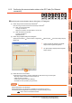
POINTPOINTPOINT
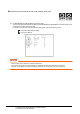
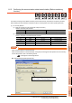
When monitoring GS230 on Numerical Display
When monitoring GS230 on Numerical Display, check [mask processing] with data operation tab as the following.
For the data operation, refer to the following manual.
GT Designer3 Screen Design Manual
Numerical Display (Data Operation tab)
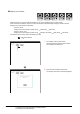
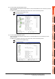
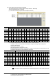
Device b15 to b8 b7 to b0
GS230 (00
H fixed) No. of faulty stations
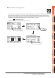
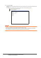
Channel Device b15 to b8 b7 to b0
Ch1 GS280 (00
H fixed) No. of faulty stations
Ch2 GS300 (00
H fixed) No. of faulty stations
Ch3 GS320 (00
H fixed) No. of faulty stations
Ch4 GS340 (00
H fixed) No. of faulty stations
Set [mask processing] to the upper eight bits (b8
to b15) of GS230 on Numerical Display.