
User's Manual

22. FA TRANSPARENT FUNCTION
22.6 Personal Computer Side Setting
22 - 57
17
ROBOT
CONTROLLER
CONNECTION
18
CNC CONNECTION
19
GOT MULTI-DROP
CONNECTION
20
MULTIPLE-GT14, GT12,
GT11, GT10
CONNECTION FUNCTION
21
MULTI-CHANNEL
FUNCTION
22
FA TRANSPARENT
FUNCTION
When connecting the GOT and personal
computer in Ethernet connection (GT16,
GT15 and GT14 only)
(1) Connecting the GOT and PLC in bus connection or
direct CPU connection
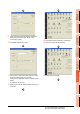
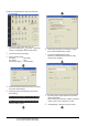
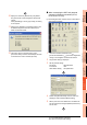
10.Specify the number for [Network No.] and [Station
No.] same as the number assigned to the Ethernet
module.
When [QnUDE(H)] is set for [Type name], the setting
is not required.
11. Specify the IP address for [IP address] same as the
IP address assigned to the built-in Ethernet port
QCPU or Ethernet module.
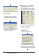
12.The screen returns to [Transfer setup]. Click
[Connection Test] to check if GX Developer has been
connected to the motion controller (Q mode).
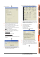
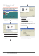
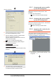
1. Click the Connection Destination view
[Connection Destination] [(Connection target data
name)] in the Navigation window of MT Works2.
2. The [Transfer Setup] is displayed.
3. Set the [Transfer Setup]:
PC side I/F : Ethernet Board
PLC side I/F : GOT
Other Station Setting : No Specification:
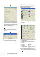
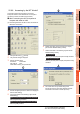
4. Double-click [Ethernet Board] of the PC side I/F to
display [PC side I/F Ethernet Board Setting].
5. Set the protocol to TCP. Network No. and Station No.
are not required to be changed (default) because they
are not used.