
User's Manual

22. FA TRANSPARENT FUNCTION
22.6 Personal Computer Side Setting
22 - 45
17
ROBOT
CONTROLLER
CONNECTION
18
CNC CONNECTION
19
GOT MULTI-DROP
CONNECTION
20
MULTIPLE-GT14, GT12,
GT11, GT10
CONNECTION FUNCTION
21
MULTI-CHANNEL
FUNCTION
22
FA TRANSPARENT
FUNCTION
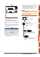
(3) Connecting the GOT and PLC in Ethernet
connection
(a) Connecting to QCPU (Q mode)
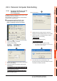
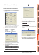
1. Click the Connection Destination view
[Connection Destination] [(Connection target data
name)] in the Navigation window of GX Works2.
2. The [Transfer Setup Connection1] is displayed.
3. Set the [Transfer Setup Connection1]:
PC side I/F : Serial USB
PLC side I/F : GOT
Other Station Setting : No Specification
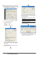
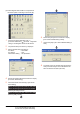
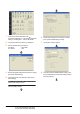
4. Double-click [Serial USB] of the PC side I/F to display
[PC side I/F Serial Setting].
5. Check-mark either of the following in [PC side I/F
Serial Setting].
Mark the [RS-232C] checkbox.
Mark the [USB] checkbox.
When connecting the GOT and PC with serial
When connecting the GOT and PC with USB
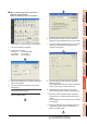
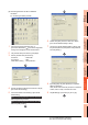
6. Double-click [GOT] of the PLC side I/F to display
[PLC side I/F Detailed Setting of GOT].
7. On the [PLC side I/F Detailed Setting of GOT], mark
the [via GOT(Ethernet) transparent mode] checkbox
and click [Setting...].
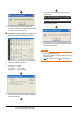
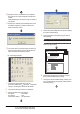
8. By clicking [Set], the [GOT (Ethernet) Transparent
Setting] is displayed.
Here, set the built-in Ethernet port QCPU or Ethernet
module, which is firstly connected via a GOT.
9. Set [QnUDE(H)] or [QJ71E71] for [PLC Type].