
User's Manual

1. PREPARATORY PROCEDURES FOR MONITORING
1.6 Checking for Normal Monitoring
1 - 39
1
PREPARATORY
PROCEDURES FOR
MONITORING
2
DEVICE RANGE
THAT CAN BE SET
3
ACCESS RANGE
FOR MONITORING
4
HOW TO MONITOR
REDUNTANT
SYSTEM
5
BUS CONNECTION
6
DIRECT
CONNECTION TO
CPU
7
COMPUTER LINK
CONNECTION
8
ETHERNET
CONNECTION
1.6 Checking for Normal Monitoring
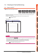
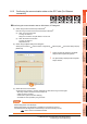
1.6.1 Check on the GOT
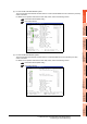
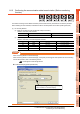
Check for errors occurring on the GOT
Presetting the system alarm to project data allows you to identify errors occurred on the GOT, PLC CPU, servo
amplifier and communications.
For details on the operation method of the GOT Utility screen, refer to the following manual.
GT User's Manual
(When using GT15)
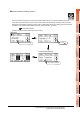
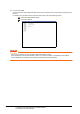
HINTHINTHINT
Advanced alarm popup display
With the advanced alarm popup display function, alarms are displayed as a popup display regardless of whether
an alarm display object is placed on the screen or not (regardless of the display screen).
Since comments can be flown from right to left, even a long comment can be displayed all.
For details of the advanced popup display, refer to the following manual.
GT Designer3 Screen Design Manual
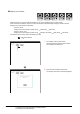
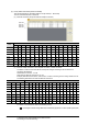
Error code Communication Channel No.
Error message Time of occurrence
(Displayed only for errors)