
User's Manual

20 - 4
20. MULTIPLE-GT14, GT12, GT11, GT10 CONNECTION FUNCTION
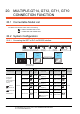
20.2 System Configuration
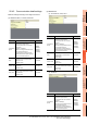
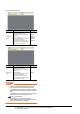
20.2.2 Connecting the GOT to PLC via RS-422 interface
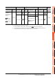
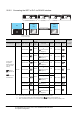
*1 When GT14, GT12, GT11 and GT10 are intermingled, the Multiple connection function is not supported.
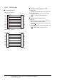
*2 The 2nd GOT must be a GT10 (input power supply: 24V) RS-232 built-in product.
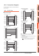
*3 For the connection to GOT, refer to the connection diagram.( RS232 connection diagram 2))
*4 When connected to the Computer link, the multiple connection function supports only QCPU (Q mode), LCPU.
MELSEC-FX
Communication driver
Communication driver
MELSEC-A
( For GT10)
GOT
(1st)
GOT
(2nd)
PLC
Varies according to
the connection type.
Connection cable
Communication driver
QnA/L/Q CPU
( For GT10)
( For GT14, GT12, GT11)
Communication driver
A/QnA/L/Q CPU,LJ71C24,QJ71C24
PLC
GOT (1st)
*1
Connection cable
GOT (2nd)
*1
Number of
connectable
equipment
Connection type
Communica
tion type
Option device Model
Commun
ication
type
Cable model
Max.
distance
Option device Model
For the system
configuration
between a got and
A plc, refer to the
following.
DIRECT
CONNECTION TO
CPU
COMPUTER LINK
CONNECTION
*4
RS-422
-
(Built into GOT)
RS-232
GT01-C30R2-9S(3m)
or
RS232 connection
diagram 1)
15m
-
(Built into GOT)
2 GOTs
-
(Built into GOT)
RS-232
GT01-C30R2-9S(3m)
or
RS232 connection
diagram 1)
15m
-
(Built into GOT)
-
(Built into GOT)
RS-232
GT01-C30R2-9S(3m)
or
RS232 connection
diagram 1)
15m
-
(Built into GOT)
-
(Built into GOT)
RS-232
GT01-C30R2-9S(3m)
or
RS232 connection
diagram 1)
15m
-
(Built into GOT)
-
(Built into GOT)
RS-232
GT10-C30R2-6P(3m)
*3
3m
-
(Built into GOT)
*2
GT10-C02H-6PT9P (0.2m)
+
RS232 connection
diagram 4)
15m
-
(Built into GOT)
RS-232
RS232 connection
diagram 3)
15m
-
(Built into GOT)
*2
-
(Built into GOT)
RS-232
GT01-C30R2-6P(3m) 3m
-
(Built into GOT)
GT10-C02H-6PT9P (0.2m)
+
RS232 connection
diagram 5)
15m