
User's Manual

1. PREPARATORY PROCEDURES FOR MONITORING
1.4 Connection Cables for the Respective Connection
1 - 29
1
PREPARATORY
PROCEDURES FOR
MONITORING
2
DEVICE RANGE
THAT CAN BE SET
3
ACCESS RANGE
FOR MONITORING
4
HOW TO MONITOR
REDUNTANT
SYSTEM
5
BUS CONNECTION
6
DIRECT
CONNECTION TO
CPU
7
COMPUTER LINK
CONNECTION
8
ETHERNET
CONNECTION
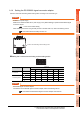
1.4.2 Coaxial cable connector connection method
The following describes the method for connecting the BNC connector (connector plug for coaxial cable) and the cable.
Precautions for soldering
Note the following precautions when soldering the internal conductor and contact.
• Make sure that the solder does not bead up at the soldered section.
• Make sure there are no gaps between the connector and cable insulator or they do not cut into each other.
• Perform soldering quickly so the insulation material does not become deformed.
CAUTION
Solder the coaxial cable connectors properly.
Insufficient soldering may result in malfunctions.
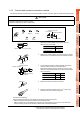
Nut Washer Gasket
Clamp Contact
Components of the BNC connector
Plug shell
Outer sheath
External conductor
Insulating material
Internal conductor
Structure of the coaxial cable
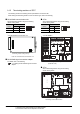
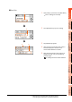
1. Remove the external sheath of the coaxial cable with
dimensions as shown below.
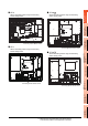
2. Pass the nut, washer, gasket, and clamp through the coaxial
cable as shown on the left and loosen the external conductor.
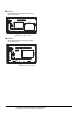
3. Cut the external conductor, insulting material, and internal
conductor with the dimensions as shown below.
Note that the external conductor should be cut to the same
dimension as the tapered section of the clamp and smoothed
down to the clamp.
4. Solder the contact to the internal conductor.
5. Insert the connector assembly shown in into the plug
shell and screw the nut into the plug shell.
A
Cut this portion of the outer sheath
Cable in use
A
3C-2V 15mm
5C-2V, 5C-2V-CCY 10mm
Clamp
Gasket
Washer
Nut
Internal conductor
Insulating material
C
B
Clamp and external
conductor
Cable in use
B C
3C-2V 6mm 3mm
5C-2V, 5C-2V-CCY 7mm 5mm
Solder here