
User's Manual

19. GOT MULTI-DROP CONNECTION
19.4 Connection Diagram
19 - 19
17
ROBOT
CONTROLLER
CONNECTION
18
CNC CONNECTION
19
GOT MULTI-DROP
CONNECTION
20
MULTIPLE-GT14, GT12,
GT11, GT10
CONNECTION FUNCTION
21
MULTI-CHANNEL
FUNCTION
22
FA TRANSPARENT
FUNCTION
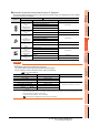
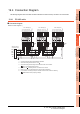
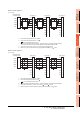
*1 Set the terminating resistor selector to "OPEN".
*2 Set the terminating resistor selector to "110 ".
1.4.3 Terminating resistors of GOT
*3 Set the 1pair/2pair signal selection switch to "1pair" when using the connection conversion adapter.
In that case, transition wiring is not necessary between SDA and RDA or SDB and RDB.
*4 This is the connector pin No. of GT14, GT11, GT105 , or GT104 main unit.
*5 Make sure to ground a cable shield line by applying Class D Grounding (100 or less).
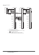
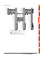
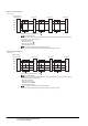
*1 Set the terminating resistor selector to "OPEN".
*2 Set the terminating resistor selector to "330 ".
1.4.3 Terminating resistors of GOT
*3 Set the 1pair/2pair signal selection switch to "2pair" when using the connection conversion adapter.
*4 This is the connector pin No. of GT14, GT11, GT105 , or GT104 main unit.
*5 Make sure to ground a cable shield line by applying Class D Grounding (100 or less).
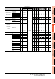
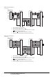
RS485 connection diagram 4)
(For 1 pair wiring)
GOT side
*
1
*
3
GOT side
*
1
*
3
Serial multi drop
connection unit
1
6
2
7
5
3
8
4
9
SDA
SDB
RDA
RDB
SG
SDA
SDB
RDA
RDB
SG
RSA
RSB
CSA
CSB
*
2
*
5
1
6
2
7
5
3
8
4
9
SDA
SDB
RDA
RDB
SG
RSA
RSB
CSA
CSB
*
5
*
4
*
4
*
4
GOT side
*
2
*
3
1
6
2
7
5
3
8
4
9
SDA
SDB
RDA
RDB
SG
RSA
RSB
CSA
CSB
*
5
*
3
*
3
*
3
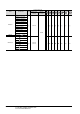
RS485 connection diagram 4)
(For 2 pair wiring)
GOT side
*
1
*
3
Serial multi drop
connection unit
1
6
2
7
5
3
8
4
9
RDA
RDB
SDA
SDB
SG
SDA
SDB
RDA
RDB
SG
RSA
RSB
CSA
CSB
*
2
*
5
GOT side
*
1
*
3
1
6
2
7
5
3
8
4
9
SDA
SDB
RDA
RDB
SG
RSA
RSB
CSA
CSB
*
5
*
4
*
4
*
4
GOT side
*
2
*
3
1
6
2
7
5
3
8
4
9
SDA
SDB
RDA
RDB
SG
RSA
RSB
CSA
CSB
*
5