
User's Manual

1 - 24
1. PREPARATORY PROCEDURES FOR MONITORING
1.3 Option Devices for the Respective Connection
When using the printer unit, sound output unit, or external I/O unit
The printer unit, sound output unit, or external I/O unit can be installed in any position (1st to 3rd stage) of the
extension interface.
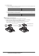
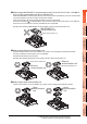
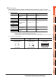
Example: When installing a printer unit
When using the video input unit, RGB input unit, video/RGB input unit, RGB output unit, or
multimedia unit
Install the video input unit, RGB input unit, video/RGB input unit, RGB output unit, or multimedia unit at the 1st stage
of the extension interface.These units cannot be used if installed in the 2nd or higher stage.
When any of these units is used, the communication units indicated below must be installed in the 2nd stage of the
extension interface.
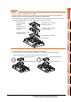
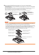
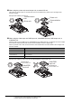
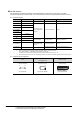
Example: When installing a video input unit and a MELSECNET/H communication unit
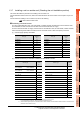
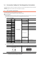
Communication unit Model
Bus connection unit GT15-QBUS2, GT15-ABUS2
MELSECNET/H communication unit GT15-J71LP23-25, GT15-J71BR13
CC-Link IE Controller Network
communication unit
GT15-J71GP23-SX
CC-Link communication unit GT15-J61BT13
Printer unit
Communication
unit
Printer unit
Communication
unit
MELSECNET/H
communication unit
Video/RGB
input unit
Video/RGB
input unit
MELSECNET/H
communication unit