
User's Manual

18. CNC CONNECTION
18.2 System Configuration
18 - 5
17
ROBOT
CONTROLLER
CONNECTION
18
CNC CONNECTION
19
GOT MULTI-DROP
CONNECTION
20
MULTIPLE-GT14, GT12,
GT11, GT10
CONNECTION FUNCTION
21
MULTI-CHANNEL
FUNCTION
22
FA TRANSPARENT
FUNCTION
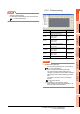
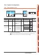
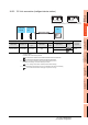
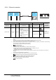
18.2.3 CC-Link connection (intelligent device station)
*1 The overall extension cable length and the length between stations vary depending on the cable type to be used and the total
number of stations.
For details, refer to the following manuals.
C6/C64/C64T CONNECTION AND MAINTENANCE MANUAL BNP-B2255
C6/C64/C64T NETWORK INSTRUCTION MANUAL BNP-B2373
*2 Specify Ver.1 as the mode setting in the Communication Settings to use it.
For details of the settings, refer to the following the manual.
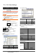
18.4.1 Setting communication interface (Communication settings)
*3 For the specifications and inquiries of the CC-Link dedicated cable, refer to the following.
CC-Link Partner Association's home page: http://www.cc-link.org/
CC-Link Ver2(ID)
Communication driver
(When MODEL GT15-J61BT13
CC-Link communication unit is used)
CC-Link(ID)
(When MODEL GT15-75J61BT13-Z
CC-Link communication unit is used)
Communication driver
Expansion
unit
GOT
Connection cable
MELDAS
C6/C64
CNC Connection cable GOT
Number of
connectable
equipment
Model name Expansion unit
Communication
type
Cable model
Max.
distance
Option device Model
MELDAS C6/C64 FUC6-HR865 CC-Link(ID)
CC-Link dedicated
cable
*3
*1
GT15-J61BT13
*2
26 GOTs
GT15-75J61BT13-Z