
User's Manual


16 - 20
16. SERVO AMPLIFIER CONNECTION
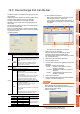
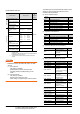
16.6 Device Range that Can Be Set
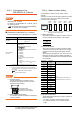
(3) MELSERVO-J2M-*DU
*1 Use PRM0 to PRM84 when writing parameters to the servo
amplifier RAM.
PRM1000 to PRM1084 are used when writing parameters to
E
2
PROM of the servo amplifier.
*2 The GOT cannot read or write data from/to consecutive
devices.
POINTPOINTPOINT
Precautions for SP, OM, TMB, TMI, TMO, and TMD
devices
(1) For bit devices
Only writing is possible.
[Alternate] of a bit switch cannot be used.
Use [Set], [Reset], and [Momentary] of a bit
switch.
(2) For word devices
Only writing is possible.
Numerical input cannot be used.
When writing, use [Word Set] of a data set switch.
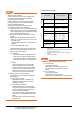
The following shows correspondences between virtual
devices for servo amplifier and data of the servo
amplifier used with the GOT.
(a) Servo amplifier request
(b) Operation mode selection
(c) Instruction demand (for test operation)
(d) Basic parameter/expansion parameter
(Continued to next page)
Device name
*2
Setting range
Device
No.
represent
ation
Bit device
Servo amplifier request
(SP)
SP0 to SP6
Decimal
Operation mode selection
(OM)
OM0 to OM4
Instruction demand
(for test operation) (TMB)
TMB0 to TMB1
Word device
Basic parameter
Expansion parameter
(PRM)
*1
PRM0 to PRM84
PRM1000 to PRM1084
Status display (ST) ST0 to ST10
Alarm (AL)
AL0
AL11 to AL21
AL200 to AL205
AL210 to AL215
AL230 to AL235
Input signal for test
operation
(for test operation) (TMI)
TMI0
Forced output of signal pin
(for test operation) (TMO)
TMO0
Set data
(for test operation) (TMD)
TMD0 to TMD2
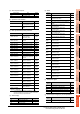
Device
name
Item Symbol
SP0 Status display data clear ―
SP1 Current alarm clear ―
SP2 Alarm history clear ―
SP3 External input signal prohibited ―
SP4 External output signal prohibited ―
SP5 External input signal resumed ―
SP6 External output signal resumed ―
Device
name
Item Symbol
OM0 Normal mode (not test operation mode) ―
OM1 JOG operation ―
OM2 Positioning operation ―
OM3 Motorless operation ―
OM4 Output signal (DO) forced output ―
Device name Item Symbol
TMB0
Clears acceleration/
deceleration time constant
(test mode)
―
TMB1
Temporary stop command
(test mode)
―
Device name Item
Symbol
*1
PRM0, PRM1000 For manufacturer setting ―
PRM1, PRM1001 Function selection 1 *OP1
PRM2, PRM1002 Auto tuning ATU
PRM3, PRM1003
CMX Electronic gear
numerator
(Command pulse multiplying
factor numerator)
CMX
PRM4, PRM1004
Electronic gear
denominator
(Command pulse multiplying
factor denominator)
CDV
PRM5, PRM1005 In-position range INP
PRM6, PRM1006 Position loop gain 1 PG1
PRM7, PRM1007
Position command
acceleration/deceleration
time constant
(position smoothing)
PST
PRM8 to PRM15,
PRM1008 to PRM1015
For manufacturer setting ―
PRM16, PRM1016 Alarm history clear *BPS
PRM17 to PRM18,
PRM1017 to PRM1018
For manufacturer setting ―
PRM19, PRM1019 DRU parameter block *BLK
PRM20, PRM1020 Function selection 2 *OP2
PRM21, PRM1021
Function selection 3
(Command pulse selection)
*OP3
PRM22, PRM1022 Function selection 4 *OP4
PRM23, PRM1023 Feed forward gain FFC