
User's Manual


15. INVERTER CONNECTION
15.7 Precautions
15 - 47
9
MELSECNET/H
CONNECTION (PLC
TO PLC NETWORK)
10
MELSECNET/10
CONNECTION (PLC
TO PLC NETWORK)
11
CC-Link IE CONTROLLER
NETWORK
CONNECTION
12
CC-Link IE FIELD
NETWORK
CONNECTION
13
CC-Link CONNECTION
(INTELLIGENT DEVICE
STATION)
14
CC-Link
CONNECTION
(Via G4)
15
INVERTER
CONNECTION
16
SERVO AMPLIFIER
CONNECTION
15.7 Precautions
Station No. of inverter system
Make sure to establish inverter system with No.0
station.
Number of inverter
Up to 31 inverters can be connected.
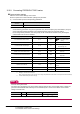
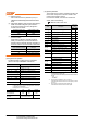
For GT11 and GT10, refer to the following manual for
the procedure to check the connectable inverter
depending on the version.
GT11 User's Manual, GT10 User's Manual
Parameter setting
(1) Communication parameter change
Do not make any change for each communication
parameter of the inverter side from GOT.
If changed, the communication to the inverter cannot
be made.
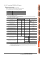
(2) When setting "8888" or "9999" to inverter parameter
(Pr)
"8888" and "9999" designate special function. When
specifying from the GOT, it will be as follows.
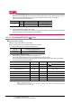
Screen switching devices, system
information devices
Make sure to use GD for screen switching devices and
system information devices when the GOT is
connected to only the inverter.
GOT clock control
Since the inverter does not have a clock function, the
settings of [time adjusting] or [time broad cast] by GOT
clock control will be disabled.
Model name Hardware version
Number of connect-
able Inverter
GT1155-QTBD
C or later 31
B or earlier 10
GT1155-QSBD
GT1150-QLBD
F or later 31
E or earlier 10
GT1055-QSBD
GT1050-QBBD
C or later 31
B or earlier 10
GT1045-QSBD
GT1040-QBBD
A or later 31
GT1030-L D
GT1030-H D
B or later 31
A or earlier 10
GT1020-L D
E or later 31
D or earlier 10
Set value of inverter side Value specified by GOT
8888 65520
9999 65535