
User's Manual


15. INVERTER CONNECTION
15.2 System Configuration
15 - 13
9
MELSECNET/H
CONNECTION (PLC
TO PLC NETWORK)
10
MELSECNET/10
CONNECTION (PLC
TO PLC NETWORK)
11
CC-Link IE CONTROLLER
NETWORK
CONNECTION
12
CC-Link IE FIELD
NETWORK
CONNECTION
13
CC-Link CONNECTION
(INTELLIGENT DEVICE
STATION)
14
CC-Link
CONNECTION
(Via G4)
15
INVERTER
CONNECTION
16
SERVO AMPLIFIER
CONNECTION
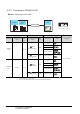
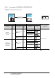
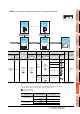
When connecting to multiple inverters (Max. 31) (Using the control terminal option)
*1 Connect it to the RS-232 interface (built into GOT). It cannot be mounted on GT1655 and GT155 .
*2 The control terminal option and the PU port cannot be used at the same time.
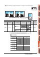
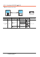
*3 For GT11 and GT10, the number of connectable inverters differs according to the hardware version.
For the procedure to check the hardware version, refer to the following manual.
GT11 User’s Manual
GT10 User’s Manual
FREQROL 500/700
Communication driver
Inverter
GOT
Connection cable
Inverter
Control
terminal
option
Control
terminal
option
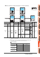
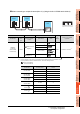
Inverter Connection cable GOT
Max.
distance
Number of
connectable
equipment
Model name
Control terminal
option
Communi
cation
type
Connection diagram
number
Option device Model
FREQROL-
E700
*2
FR-E7TR
*2
RS-422
RS422 connection
diagram 8)
GT16-C02R4-9S(0.2m)
500m
31 inverters for
one GOT
*3
GT15-RS2T4-9P
*1
GT15-RS4-9S
- (Built into GOT)
RS422 connection
diagram 16)
- (Built into GOT)
Model name Hardware version
Number of connectable
Inverter
GT1155-QTBD
C or later 31
B or earlier 10
GT1155-QSBD
GT1150-QLBD
F or later 31
E or earlier 10
GT1055-QSBD
GT1050-QBBD
C or later 31
B or earlier 10
GT1045-QSBD
GT1040-QBBD
A or later 31
GT1030-L D
GT1030-H D
B or later 31
A or earlier 10
GT1020-L D
E or later 31
D or earlier 10