
User's Manual

13. CC-Link CONNECTION (INTELLIGENT DEVICE STATION)
13.3 GOT Side Settings
13 - 9
9
MELSECNET/H
CONNECTION (PLC
TO PLC NETWORK)
10
MELSECNET/10
CONNECTION (PLC
TO PLC NETWORK)
11
CC-Link IE CONTROLLER
NETWORK
CONNECTION
12
CC-Link IE FIELD
NETWORK
CONNECTION
13
CC-Link CONNECTION
(INTELLIGENT DEVICE
STATION)
14
CC-Link
CONNECTION
(Via G4)
15
INVERTER
CONNECTION
16
SERVO AMPLIFIER
CONNECTION
13.3 GOT Side Settings
13.3.1 Setting communication
interface (Communication
settings)
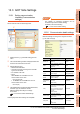
Set the channel of the connected equipment.
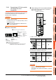
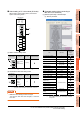
1. Select [Common] [Controller Setting] from the
menu.
2. The Controller Setting window is displayed. Select the
channel to be used from the list menu.
3. Set the following items.
• Manufacturer: Mitsubishi
• Controller Type: Set according to the Controller
Type to be connected.
• I/F: Interface to be used
• Driver:
When MODEL GT15-J61BT13 CC-Link
communication unit is used
CC-Link Ver2 (ID)
When MODEL GT15-75J61BT13-Z CC-Link
communication unit is used
CC-Link (ID)
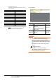
4. The detailed setting is displayed after Manufacturer,
Controller Type, I/F, and Driver are set.
Make the settings according to the usage
environment.
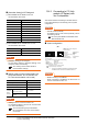
13.3.2 Communication detail settings
Click the [OK] button when settings are completed.
POINTPOINTPOINT
The settings of connecting equipment can be
confirmed in [I/F Communication Setting].
For details, refer to the following.
1.1.2 I/F communication setting
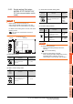
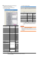
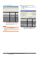
13.3.2 Communication detail settings
Make the settings according to the usage environment.
(1) CC-Link Ver.2 (ID)
2.
3.
4.
Click!
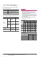
Item Description Range
Station No.
Set the station No. of the GOT.
(Default: 1)
1 to 64
Transmission
Rate
*1
Set the transmission speed and
the mode of the GOT.
(Default: 0)
0 to E
Mode
Set the mode of CC-Link.
(Default: Ver.1)
Ver.1/Ver.2/
Additional/Offline
Expanded
Cyclic
Set the cyclic point expansion.
(Default: Single)
Single/Double/
Quadruple/Octuple
Occupied
Station
Set the number of stations
occupied by the GOT.
(Default: 1 Station)
1 Station/4 Stations
Input for Error
Station
Set Clear/Hold at an error
occurrence.
(Default: Clear)
Clear/Hold
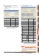
Retry
Set the number of retries to be
performed when a communication
timeout occurs.
When no response is received
after retries, a communication
times out.
(Default: 3times)
0 to 5times
Timeout Time
Set the time period for a
communication to time out.
(Default: 3sec)
3 to 90sec
Delay Time
Set the delay time for reducing the
load of the network/destination
PLC.
(Default: 0ms)
0 to 300 (ms)