
User's Manual

10. MELSECNET/10 CONNECTION (PLC TO PLC NETWORK)
10.4 PLC Side Setting
10 - 23
9
MELSECNET/H
CONNECTION (PLC
TO PLC NETWORK)
10
MELSECNET/10
CONNECTION (PLC
TO PLC NETWORK)
11
CC-Link IE CONTROLLER
NETWORK
CONNECTION
12
CC-Link IE FIELD
NETWORK
CONNECTION
13
CC-Link CONNECTION
(INTELLIGENT DEVICE
STATION)
14
CC-Link
CONNECTION
(Via G4)
15
INVERTER
CONNECTION
16
SERVO AMPLIFIER
CONNECTION
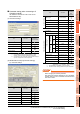
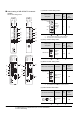
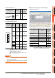
(5) Mode setting switch
: Necessary : As necessary : Not necessary
(6) Condition setting switches
: Necessary : As necessary : Not necessary
*1 The MELSECNET/10 network module can be communicated
by default parameters.
For details, refer to the following manual.
Type MELSECNET/10 Network system (PLC to PLC
network) Reference Manual
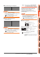
POINTPOINTPOINT
When the switch setting (other than the LED indication
select switch) is changed
Turn the PLC CPU OFF then ON again, or reset the
PLC CPU.
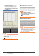
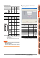
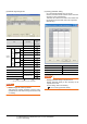
[Network parameter] of GX Developer
(1) Network parameter
: Necessary : As necessary : Not necessary
*1 Specify the same network No. as that of the network number
setting switch of the MELSECNET/10 network module.
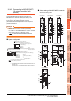
Mode setting switch Description
Set
value
Setting
necessity at
GOT
connection
Mode setting
(Online)
0
(fixed)
Condition setting
switches
Setting
switch
Description
Set
value
Setting
necessity at
GOT
connection
SW1
Network type
(PLC to PLC
net-work
(PC))
OFF
(fixed)
SW2
Station type
(Control
station
(MNG))
ON
(fixed)
SW3
Parameter
for using
*1
(common
parameter
(PRM))
OFF
(fixed)
SW4
No. of
stations*1
OFF
(fixed)
SW5
SW6
Total B /W
points*1
OFF
(fixed)
SW7
SW8 Not used
OFF
(fixed)
F
7
E
6
D
5
C
4
B
3
A
2
9
1
0
8
MODE
0:ONLINE(A.R)
2:OFFLINE
OFF ON
SW
1
2
3
4
5
6
7
8
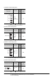
Item Set value
Setting
necessity at
GOT
connection
Network type
MNET/10
(Control station) (fixed)
Start I/O No. 0000
H
Network No.*1 1
Total stations 2
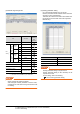
Network range assignment Refer to (2)
Refresh parameters
(Use default value)
Interlink transmission
parameters
Routing parameters Refer to (3)