
User's Manual


10 - 12
10. MELSECNET/10 CONNECTION (PLC TO PLC NETWORK)
10.4 PLC Side Setting
10.4 PLC Side Setting
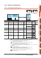
10.4.1 Connecting to MELSECNET/H
network module
This section describes the settings of the GOT and
MELSECNET/H network module in the following case of
system configuration.
When connecting the MELSECNET/H network module to
the MELSECNET/10 network system, specify the
MELSECNET/10 Mode as a network type.
POINTPOINTPOINT
MELSECNET/H network module
For details of the MELSECNET/H network module,
refer to the following manual.
Q corresponding MELSECNET/H Network
System Reference Manual (PLC to PLC
network)
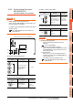
System configuration
*1 The MELSECNET/H network module is mounted at slot 0 of
the base unit.
The start I/O No. of the MELSECNET/H network module is
set at "0".
POINTPOINTPOINT
When connecting to Q170MCPU
When connected to Q170MCPU, the start I/O No. of
the MELSECNET/H network module is set to "70".
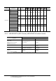
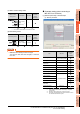
Switch setting of MELSECNET/H network
module
Set the station number setting switch and mode setting
switch.
Model name Reference
MELSECNET/H network module
QJ71LP21,
QJ71LP21-25,
QJ71LP21S-25,
QJ71BR11
10.4.1
MELSECNET/10 network
module
(QnA Series)
AJ71QLP21,
AJ71QLP21S,
AJ71QBR11,
A1SJ71QLP21,
A1SJ71QLP21S,
A1SJ71QBR11
10.4.2
MELSECNET/10 network
module
(A Series)
AJ71LP21,
AJ71BR11,
A1SJ71LP21,
A1SJ71BR1
10.4.3
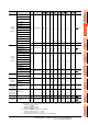
<MELSECNET/H network module> *1
(Use the default value for settings other than the following.)
Station No. : 1
Mode : Online (10Mbps)
Network type : MNET/10 mode (Control station)
Network No. : 1
Total stations : 2
Network range assignment: LB0000
H to LB00FFH
MELSECNET/10 (PLC to PLC network)
<GOT> (Use the default value for settings other
than the following.)
Station No. : 2
Mode : Online
Network No. : 1
Network range assignment: LB0100
H
to LB01FF
H
LW0100H to LW01FFH
LW0000H to LW00FFH
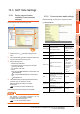
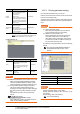
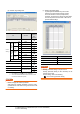
■ [Controller Setting] of GT Designer3
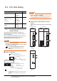
■ Setting of the MELSECNET/10 communication unit
MNG
D.LINK
RD
L ERR.
RUN
T.PASS
SD
ERR.
QJ71LP21-25
0
5
9
4
8
3
7
2
6
1
0
5
9
4
8
3
7
2
6
1
STATION NO.
X10
X1
MODE
0
8
F
7
E
6
D
5
C
4
B
A
3
2
9
1
QJ71LP21
-25
IN
OUT
EXT.PW
+24V
24G
24G
0
5
9
4
8
3
7
2
6
1
0
5
9
4
8
3
7
2
6
1
STATION NO.
X10
X1
MODE
0
8
F
7
E
6
D
5
C
4
B
A
3
2
9
1
IN
OUT
MNG
D.LINK
RD
L ERR.
RUN
T.PASS
SD
ERR.
QJ71LP21S-25
QJ71LP21 S-25
EXT.PW
EXT.PW
+24V
24G
(FG)
MNG
D.LINK
RD
L ERR.
RUN
T.PASS
SD
ERR.
0
5
9
4
8
3
7
2
6
1
0
5
9
4
8
3
7
2
6
1
STATION NO.
X10
X1
MODE
0
8
F
7
E
6
D
5
C
4
B
A
3
2
9
1
QJ71BR11
QJ71BR11
(1)
(2)
(1)
(2)
(1)
(2)
QJ71LP21, QJ71LP21-25 QJ71LP21S-25
QJ71BR11