
User's Manual

A - 30
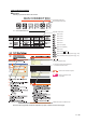
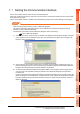
About system configuration
The following describes the system configuration of each connection included in this manual.
Since the above page was created for explanation purpose, it differs from the actual page.
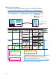
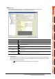
The configuration of The configuration of
equipment connected equipment connected
to GOT is shown.to GOT is shown.
The cable connecting The cable connecting
the GOT to the the GOT to the
equipment is shown.equipment is shown.
The configuration of The configuration of
the GOT connected to the GOT connected to
equipment is shown.equipment is shown.
RS-422 connector
conversion Cable
QCPU GOT
Connection cable
A representative example
of the system configuration
is described with an
illustration.
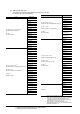
Indicates the connection diagram
number of cables to be prepared by
the user.
Refer to the connection diagram
section in each chapter.
Indicates the commercially available
cable models that can be used.
Indicates the maximum distance between
the PLC and GOT.
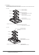
1) Connect the RS-422 conversion cable [FA-CNV2402CBL] to the [MELSEC-Q].
2) Connect the option [GT16-C02R4-9S] to [GT16].
3) Connect [MELSEQ-Q] and [GT16] with the connection cable [GT01-C30R4-25P].
System Configuration ExamplesSystem Configuration Examples
(When connecting the PLC [MELSEC-Q] and GT16, with RS-422 cable)
System Configuration Examples
The configuration of
equipment connected
to GOT is shown.
The cable connecting
the GOT to the
equipment is shown.
The configuration of
the GOT connected to
equipment is shown.
For the option devices,
refer to the following.
1.3 Option Devices for
the Respective
Connection