
User's Manual


8. ETHERNET CONNECTION
8.5 Precautions
8 - 49
1
PREPARATORY
PROCEDURES FOR
MONITORING
2
DEVICE RANGE
THAT CAN BE SET
3
ACCESS RANGE
FOR MONITORING
4
HOW TO MONITOR
REDUNTANT
SYSTEM
5
BUS CONNECTION
6
DIRECT
CONNECTION TO
CPU
7
COMPUTER LINK
CONNECTION
8
ETHERNET
CONNECTION
8.5 Precautions
Connection to QnA (S) CPU type
Use B or a later function version of Ethernet module
(QnA Series) and PLC CPU (QnA/QnASCPU type).
Connection to QSCPU
The GOT can only read device data and sequence
programs by the ladder monitor function in the QSCPU.
The GOT cannot write any data to the QSCPU.
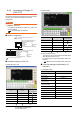
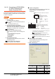
Connection to Q170MCPU
Set [CPU No.] to "2" in the device setting to monitor the
device of the Motion CPU area (CPU No.2).
When the CPU No. is set to "1", the device on the PLC
CPU area (CPU No.1) is monitored.
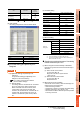
When the CPU No. is set to "0", the monitoring target
differs depending on the GOT connection destination.
Refer to the following.
When the CPU No. is set to the number other than "0"
to "2", a communication error occurs and the monitoring
cannot be executed.
For setting the CPU No., refer to the following manual.
GT Designer3 Version Screen Design
Manual
Example) Setting dialog box of the bit device
Connection in the multiple CPU system
When the GOT is connected to multiple CPU system,
the following time is taken until when the PLC runs.
QCPU (Q mode), motion controller CPU (Q series): 10
seconds or more
MELDAS C70: 18 seconds or more
When the GOT starts before the PLC runs, a system
alarm occurs. Adjust the opening screen time in the
GOT setup so that no system alarm occurs.
GT Designer3 Version Screen Design
Manual
Connection to LCPU
LCPU may diagnose (check file system, recovering
process, etc.) the SD memory card when turning on the
power or when resetting. Therefore, it takes time until
the SD memory card becomes available. When the
GOT starts before the SD card becomes available, a
system alarm occurs. Adjust the opening screen time in
the GOT setup so that no system alarm occurs.
GT Designer3 Version Screen Design
Manual
When connecting to multiple GOTs
(1) Setting PLC No.
When connecting two or more GOTs in the Ethernet
network, set each [PLC No.] to the GOT.
8.3.1 Setting communication interface
(Communication settings)
(2) Setting IP address
Do not use the IP address "192.168.0.18" when using
multiple GOTs.
A communication error may occur on the GOT with the
IP address.
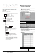
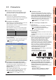
(3) Setting for starting up multiple GOTs simultaneously
(When connected to Built-in Ethernet port CPU)
When connecting multiple GOTs to one Built-in
Ethernet port CPU, adjust the timing of GOT
communication start. When the communication
concentrates on the PLC, the communication between
GOT and PLC becomes difficult, and the monitoring by
GOT may not start. As a method for adjusting the
timing, communicating one GOT alone first, and then
communicating the other GOTs is effective.
Set the following items on each GOT.
• [Startup Time] of [Controller Setting], or [Title Display
Time] of [GOT Setup].
• [Timeout Time] of [Controller Setting]
The following shows a setting example.
When connecting to the multiple network
equipment (including GOT) in a segment
By increasing the network load, the transmission speed
between the GOT and PLC may be reduced.
The following actions may improve the communication
performance.
• Using a switching hub
• More high speed by 100BASE-TX (100Mbps)
• Reduction of the monitoring points on GOT
GOT connection destination Monitoring target
QJ71E71 module PLC CPU area (CPU No.1)
PERIPHERAL I/F Motion CPU area (CPU No.2)
QnUDE(H)CPU
GOT2
GOT1
GOT10
Startup Time
GOT1 GOT2
GOT10
Item
Timeout Time
3sec (default)
3sec (default)
4sec 4sec
4sec 4sec
HUB