
User's Manual

8. ETHERNET CONNECTION
8.4 PLC Side Setting
8 - 29
1
PREPARATORY
PROCEDURES FOR
MONITORING
2
DEVICE RANGE
THAT CAN BE SET
3
ACCESS RANGE
FOR MONITORING
4
HOW TO MONITOR
REDUNTANT
SYSTEM
5
BUS CONNECTION
6
DIRECT
CONNECTION TO
CPU
7
COMPUTER LINK
CONNECTION
8
ETHERNET
CONNECTION
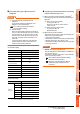
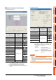
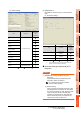
(d) System settings
: Necessary : As necessary : Not necessary
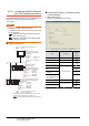
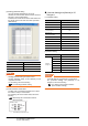
(2) Q24DHCCPU-V
Use SW4PVC-CCPU-E for the C Controller setting
utility.
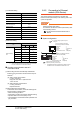
(a) Connection settings
: Necessary : As necessary : Not necessary
*1 If the IP address of the C Controller module has been
changed, input the changed IP address.
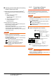
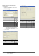
[Controller Setting] and [Ethernet] of GT
Designer3
POINTPOINTPOINT
(1) [Controller Setting] and [Ethernet] of GT
Designer3
For [Controller Setting] and [Ethernet] of GT
Designer3, refer to the following.
8.3.1 Setting communication interface
(Communication settings)
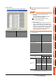
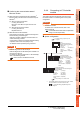
(2) Ethernet setting
When connecting C Controller module to a GOT,
the setting items for the network No. and station
No. do not exist at the PLC side. However, these
virtual values must be set on the GOT side.
Therefore, set the network No. and station No.
Set the network No. that is not existed on the
network system and any station No..
Item Set value
Setting
necessity at
GOT
connection
Points occupied by empty
slot
(Use default value)
Remote reset
Output mode at STOP to
RUN
Intelligent function module
settings
Initial settings of intelligent
function module
WDT (Watchdog timer)
setting
Error check
Operation mode at the
time of error
Module synchronization
Built-in Ethernet port open
settings
Mark the checkbox
Event history registration
settings
(Use default value)
Item Set value
Setting
necessity at
GOT
connection
IP Address
*1
192.168.3.39
(Default)
Subnet Mask
255.255.255.0
(Default)
Default Gateway -