
User's Manual

8. ETHERNET CONNECTION
8.4 PLC Side Setting
8 - 27
1
PREPARATORY
PROCEDURES FOR
MONITORING
2
DEVICE RANGE
THAT CAN BE SET
3
ACCESS RANGE
FOR MONITORING
4
HOW TO MONITOR
REDUNTANT
SYSTEM
5
BUS CONNECTION
6
DIRECT
CONNECTION TO
CPU
7
COMPUTER LINK
CONNECTION
8
ETHERNET
CONNECTION
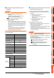
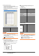
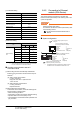
Confirming the communication state of
Ethernet module
(1) When using the Command Prompt of Windows
.
Execute a Ping command at the Command Prompt of
Windows
.
(a) When normal communication
C:\>Ping 192.168.0.19
Reply from 192.168.0.19: bytes=32 time<1ms
TTL=64
(b) When abnormal communication
C:\>Ping 192.168.0.19
Request timed out.
(2) When abnormal communication
At abnormal communication, check the followings and
execute the Ping command again.
• Mounting condition of Ethernet communication unit
• Cable connecting condition
• Confirmation of switch and network parameter setting
• Operation state of PLC CPU (faulty or not)
• IP address of GOT specified by Ping command
POINTPOINTPOINT
Ethernet diagnostics of GX Developer
Ethernet diagnostics of GX Developer is available to a
Ping test from the PLC.
For details of Ethernet diagnostics of GX Developer,
refer to the following manual.
User's manual of the Ethernet module
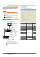
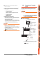
8.4.4 Connecting to C Controller
module
This section describes the settings of the GOT and C
Controller module in the following case of the system
configuration.
POINTPOINTPOINT
C Controller module
For details of C Controller module, refer to the
following manual.
C Controller Module User's Manual (Hardware
Design, Function Explanation)
System configuration
*1 These setting items do not exist at the PLC side. However,
the virtual values must be set on the GOT side.
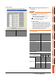
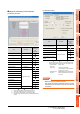
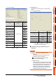
[Controller Setting] and [Ethernet] of GT
Designer3
<GOT>
(The settings other than the
following are set to the default)
Network No.
: 1
PLC No. : 1
IP address
: 192.168.3.18
Port No.
: 5001
Communication
format
: UDP(fixed)
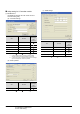
Network No.
: 1 (virtual)
PLC No.
: 2 (virtual)
IP address
: 192.168.3.1
Port No.
: 5006(fixed)
Communication
format
: UDP(fixed)
<C controller module>
(The settings other than the
following are set to the default)
1
Network No.
: 1 (virtual)
PLC No.
: 3 (virtual)
IP address
: 192.168.3.2
Port No.
: 5006(fixed)
Communication
format
: UDP(fixed)
<C controller module>
(The settings other than the following are
set to the default)
2
*1
*1
*1
*1
[Controller Setting] and [Ethernet] of GT
Designer3
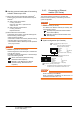
■
Utility setting for C Controller module
■
■