
User's Manual

7 - 18
7. COMPUTER LINK CONNECTION
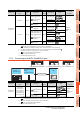
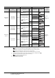
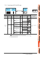
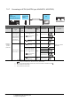
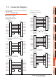
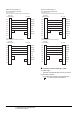
7.3 Connection Diagram
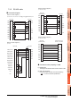
Connecting terminating resistors
(1) GOT side
When connecting a PLC to the GOT, a terminating
resistor must be connected to the GOT.
(a) For GT16, GT15, GT12
Set the terminating resistor setting switch of the
GOT main unit to "Disable".
(b) For GT14, GT11, GT10
Set the terminating resistor selector to "330 ".
For the procedure to set the terminating resistor, refer
to the following.
1.4.3 Terminating resistors of GOT
(2) Serial communication module or computer link
module side
Connect the terminating resistors (330 1/4W (orange/
orange/brown/ ) ) on the serial communication module
or computer link module side. For details, refer to the
following manual.
User's Manual for the serial communication
module or computer link module
(a) Other than A2CCPUC24(-PRF)
Connect the terminating resistors supplied with the
module across RDA and RDB.
(b) A2CCPUC24(-PRF)
Set TXD and RXD on the terminating resistor
setting pin to "A".