
User's Manual


6 - 28
6. DIRECT CONNECTION TO CPU
6.5 Precautions
6.5 Precautions
Connection to FXCPU
(1) When connecting to FX3G/FX3GC/FX3U/FX3UC series
When the keyword of FXCPU (FX3G/FX3GC/FX3U/
FX
3UC series) has been set, GOT may not be able to
monitoring.Perform an I/O check again.
( ■ Perform an I/O check) When the result of the I/
O check is normal, check the status of keyword
registration.
(2) When connecting with function extension board or
communication special adapter
When a sequence program and settings that the
FXCPU communicates with devices other than the
GOT are set with software, including GX Developer, the
FXCPU cannot communicate with the GOT.
(a) Settings with sequence program
Check the sequence program and delete the
following.
FX SERIES PROGRAMMABLE
CONTROLLERS USER'S MANUAL - Data
Communication Edition
• No protocol communication (RS instruction)
• Sequence program with the computer link, N:N
network, and parallel link
• Parameter setting
• Set the following special registers to 0.
Except FX
3U, FX3UC: D8120
FX3U, FX3UC: D8120, D8400, D8420
FX
3G, FX3GC: D8120, D8400, D8420, D8370
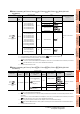
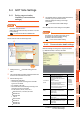
(b) Settings with GX Developer
Select [PLC parameter] in [Parameter], and then
click the PLC system(2) tab on the FX parameter
screen.
Uncheck [Operate communication setting], and
then transfer the parameter to the programmable
controller.After the transfer, turn off the
programmable controller, and then turn on the
programmable controller again.
(3) Connection to GT1020-L L , GT1030- L
When connecting GT1020-L L or GT1030- L
to FX3G series, they cannot be connected to standard
built-in port (RS-422) and function expansion board
(FX
3G-422-BD) simultaneously.
Connection in the multiple CPU system
When the GOT is connected to multiple CPU system,
the following time is taken until when the PLC runs.
• QCPU (Q mode), motion controller CPU (Q series):
10 seconds or more
• MELDAS C70: 18 seconds or more
When the GOT starts before the PLC runs, a system
alarm occurs.Adjust the opening screen time in the
GOT setup so that no system alarm occurs.
GT Designer3 Version Screen Design
Manual
Connection to LCPU
LCPU may diagnose (check file system, recovering
process, etc.) the SD memory card when turning on the
power or when resetting. Therefore, it takes time until
the SD memory card becomes available. When the
GOT starts before the SD card becomes available, a
system alarm occurs. Adjust the opening screen time in
the GOT setup so that no system alarm occurs.
GT Designer3 Version Screen Design
Manual
Connection to basic model QCPU
Do not set the serial communication function of Q00UJ/
Q00U/Q01U/Q02UCPU, Q00/Q01CPU. If the function
is set, the communication may not be performed.
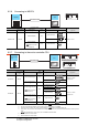
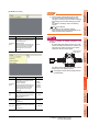
Connection to Q170MCPU
Set [CPU No.] to "2" in the device setting to monitor the
device of the Motion CPU area (CPU No.2).
When the CPU No. is set to "0" or "1", the device on the
PLC CPU area (CPU No.1) is monitored.
When the CPU No. is set to the number other than "0"
to "2", a communication error occurs and the monitoring
cannot be executed.
For setting the CPU No., refer to the following manual.
GT Designer3 Version Screen Design
Manual
Example) Setting dialog box of the bit device