
User's Manual

5 - 34
5. BUS CONNECTION
5.4 Precautions
5.4 Precautions
5.4.1 GT15-C [ ] EXSS-1,
GT15-C [ ] BS
(1) Composition of GT15-C EXSS-1
It is composed of GT15-EXCNB (0.5m) and GT15-
C BS (10 to 30m).
Calculate the cable length based on GT15-C100EXSS-
1(10m), GT15-C200EXSS-1(20m) and GT15-
C300EXSS-1(30m).
(2) GT15-C EXSS-1 connector
Connect the connectors as follows:
GT15-EXCNB PLC CPU side
GT15-C BS GOT side
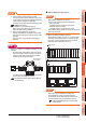
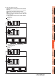
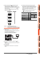
(3) Grounding
(a) When using GT15-C EXSS-1
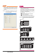
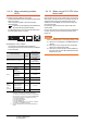
(b) When using GT15-C BS
Follow the GOT side grounding steps in (a) above
for both GOTs.
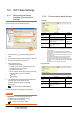
5.4.2 Turning the GOT ON
(1) System configuration
The PLC CPU remains in the reset status until the GOT
is started.
Therefore, no sequence program will run until then.
The system configuration, in which the GOT is turned
on from a sequence program, is not available.
(2) Time taken until the PLC runs after power-on of the
GOT
The following time is taken from when the GOT is
powered on until when the PLC runs.
• QCPU (Q mode), motion controller CPU
(Q series): 10 seconds or more
• MELDAS C70: 18 seconds or more
When the GOT starts before the PLC runs, a system
alarm occurs.Adjust the opening screen time in the
GOT setup so that no system alarm occurs.
GT Designer3 Version Screen Design
Manual
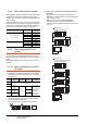
(3) Power-up sequence for connection of 3 GOTs or
more (when connecting QCPU (Q mode))
5.4.10 (1)Restrictions in overall cable length to
No. of GOTs
(4) Power-up sequence for connection of the
Q4ARCPU redundant system
5.4.14 (2)Power-On sequence for GOT and
Q4ARCPU redundant system
(5) Power-up sequence for cases other than (3) and (4)
The GOT and PLC can both be started up whichever of
these devices is turned ON first. (There is no specific
sequence in which they are powered ON)
Note, however, that operation is as follows when the
GOT is turned ON followed by the PLC:
When the PLC power is OFF with the GOT turned ON,
the system alarm (No.402: timeout error) is generated.
Upon power-on of the PLC CPU, the GOT
automatically starts monitoring.
Use System Information to reset the alarm.
For the System Information, refer to the following
manual:
GT Designer3 Version Screen Design
Manual
1. Connect the LG and FG terminals of the
terminal block on the GOT unit power and
ground them with a cable.
2. Use the GT15-C BS's FG cable of 28cm
or less.
3. Do not connect the GT15-EXCNB's FG
ground cable.
4. Connect the GT15-C BS's FG cable on
the GOT side to FG of the GOT unit power's
terminal block.
5. Connect the GT15-C BS's FG cable on
the PLC side to FG of the PLC's power
supply module.
6. Connect the LG and FG terminals of the
terminal block on the PLC and ground them
with a cable.
(GT15-EXCNB) (GT15-C□BS)
PLC side GOT side
FG
LG
N
L
PLC
Not connected
(GT15-EXCNB)
GOT
OUT IN
FGLG
NL
2SQ cables to
FG terminals,
28cm or less
2SQ cables to
FG terminals,
28cm or less
(GT15-C□BS)