
User's Manual

4. HOW TO MONITOR REDUNTANT SYSTEM
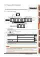
4.2 Direct CPU Connection
4 - 17
1
PREPARATORY
PROCEDURES FOR
MONITORING
2
DEVICE RANGE
THAT CAN BE SET
3
ACCESS RANGE
FOR MONITORING
4
HOW TO MONITOR
REDUNTANT
SYSTEM
5
BUS CONNECTION
6
DIRECT
CONNECTION TO
CPU
7
COMPUTER LINK
CONNECTION
8
ETHERNET
CONNECTION
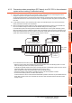
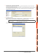
4. Set the touch switches on the base screen 1.
By using the go to screen switch function, set a touch switch for shifting the screen to the next screen with a screen
touch, when the connected PLC CPU is the control system (SM1515 is ON).
Select [Object] [Switch] [Go To Screen Switch] and set the screen switching function.
Set the same size for the touch switch as the base screen size so that touching any place of the screen enables the
switch operation.
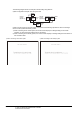
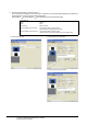
Next Screen tab
Screen Type : Base
Go To Screen : Fixed 2
Style tab
Display Style : None (Shape)
Trigger tab
Trigger Type : ON
Trigger Device : SM1515
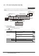
1) Next Screen tab 2) Style tab screen 3) Trigger tab screen
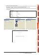
The following shows the created base screen 1.