Gravimetric Slide Gate Batch Blender Mitsubishi Controller Part Number: 882.00207.00 Bulletin Number: BF1-615 Effective: 02/01/06 Write Down Your Serial Numbers Here For Future Reference: _________________________ _________________________ _________________________ _________________________ _________________________ _________________________ We are committed to a continuing program of product improvement.
Please note that our address and phone information has changed. Please reference this page for updated contact information. These manuals are obsolete and are provided only for their technical information, data and capacities. Portions of these manuals detailing procedures or precautions in the operation, inspection, maintenance and repair of the products may be inadequate, inaccurate, and/or incomplete and shouldn’t be relied upon.
Shipping Info Unpacking and Inspection You should inspect your equipment for possible shipping damage. Thoroughly check the equipment for any damage that might have occurred in transit, such as broken or loose wiring and components, loose hardware and mounting screws, etc. In the Event of Shipping Damage According to the contract terms and conditions of the Carrier, the responsibility of the Shipper ends at the time and place of shipment.
Returns Do not return any damaged or incorrect items until you receive shipping instructions from the shipping department. Credit Returns Prior to the return of any material, authorization must be given by the manufacturer. A RMA number will be assigned for the equipment to be returned. Reason for requesting the return must be given. ALL returned material purchased from the manufacturer returned is subject to 15% ($75.00 minimum) restocking charge. ALL returns are to be shipped prepaid.
Table of Contents CHAPTER 1: SAFETY................................................................ 7 1-1 1-2 1-3 How to Use This Manual ............................................................................................. 7 Safety Symbols Used in this Manual .....................................................................7 Warnings and Precautions .......................................................................................... 9 Responsibility .......................................
3-3 3-4 3-5 3-6 Electrical Connections............................................................................................... 34 Pneumatic Connections ............................................................................................ 34 Initial Set-up .............................................................................................................. 35 Mechanical Set-up...............................................................................................
-2 7-3 7-4 7-5 7-6 7-7 Customer Responsibilities ...................................................................................71 Technical Specifications............................................................................................ 72 Equipment Specifications ....................................................................................72 Annex B Information ............................................................................................73 Drawings and Diagrams ....
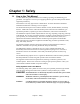
Chapter 1: Safety 1-1 How to Use This Manual Use this manual as a guide and reference for installing, operating, and maintaining your granulator. The purpose is to assist you in applying efficient, proven techniques that enhance equipment productivity. This manual covers only light corrective maintenance. No other maintenance should be undertaken without first contacting a service engineer. The Functional Description section outlines models covered, standard features, and safety features.
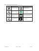
Figure 1: Safety Tags and Warning Labels Tag Description Tag Pinch Point Slide Gate Read Operation & Installation Manual Shear Point Rotating Mixer Earth Ground High Voltage Inside Enclosure PE Shear Hazard Rotating Auger 882.00207.
1-2 Warnings and Precautions Our equipment is designed to provide safe and reliable operation when installed and operated within design specifications, following national and local safety codes. This may include, but is not limited to OSHA, NEC, CSA, SPI, and any other local, national and international regulations.
1-3 Responsibility These machines are constructed for maximum operator safety when used under standard operating conditions and when recommended instructions are followed in the maintenance and operation of the machine. All personnel engaged in the use of the machine should become familiar with its operation as described in this manual. Proper operation of the machine promotes safety for the operator and all workers in its vicinity.
Learn and always use safe operation. Cooperate with co-workers to promote safe practices. Immediately report any potentially dangerous situation to your supervisor or appropriate person. REMEMBER: • NEVER place your hands or any part of your body in any dangerous location. • NEVER operate, service, or adjust the blender without appropriate training and first reading and understanding this manual.
Maintenance Responsibility Proper maintenance is essential to safety. If you are a maintenance worker, you must make safety a priority to effectively repair and maintain equipment. Before removing, adjusting, or replacing parts on a machine, remember to turn off all electric supplies and all accessory equipment at the machine, and disconnect and lockout electrical power. Attach warning tags to the disconnect switch.
Chapter 2: Functional Description 2-1 Models Covered in This Manual This manual provides operation, installation, and maintenance instructions for slide gate blenders of various blending rates and specifications. See below for a list of available models.
Figure 2: Equipment Specifications Dimensions and Specifications Maximum Blending Rate, lbs/hr (kgs/hr) (3) 150 500 900 2500 4000 6000 150 (68) 500 (227) 900 (410) 2500 (1135) 4000 (1815) 6000 (2725) Number of Materials to be Blended Slide Gate Size - Majors, in. (mm) 2 to 4 2 to 6 2.0 (50) 2.0 (50) 2.5 (63) Slide Gate Size - Minors, in. (mm) 1.5 (38) 1.5 (38) 2.0 (50) 3.0 (76) Supply Hopper Capacity - Majors, cu.ft. (l.) (4) 0.7 (20) 2.5 (70) 5.2 (145) 14.3 (400) 1.8 (50) 3.
2-3 Typical Features and Components Mechanical Features • Exclusive diamond design slide gate metering assemblies meter a large range for free flowing pellet materials • Adjustable Slide gate stroke limiting restrictors provided for accurate metering of minor ingredients (not on 150 pound model) • Removable Stainless steel weigh hopper and mixing components • Powder Coated Mild steel material supply hoppers with machined polycarbonate clean-out doors and optional material drains (stainless steel on 150 pou
• Three (3) types of recipe entry procedures available: o Quickset mode (up to 6-component) recipe entry. Color and additives are metered as a percentage of the virgin material. o Percentage mode recipe entry. Ingredients are metered as a percentage of the overall batch. o Parts mode recipe entry (i.e.
Slide Gates Air operated slide gates are provided to meter the majority of pellet ingredients on Slide Gate blenders. Note: The metering range assumes 1/8” diameter free-flowing plastic pellets weighing approximately 35 lbs./cu. ft. This is meant to be an approximate sizing recommendation and can vary with different bulk density resins, pellet configuration, etc. A stroke limiter (included) can be installed on the metering gates to limit their travel.
Figure 6: Typical Slide Gate Assembly Each of the diamond gate air cylinders is actuated by a solenoid valve, which is controlled by the blender controller. When the solenoid valve is energized, it opens the metering valve cylinder. When the solenoid valve is de-energized, it closes the metering valve cylinder. If the power is interrupted to the blender, the metering valves will return to the closed position to prevent material from over-filling the weigh hopper/mix chamber.
Figure 7: Typical Weigh Hopper Assembly The weigh hopper dump door holds the material until it is dumped into the mixing section. The cylinder is actuated by a solenoid in the valve stack on the side of the blender. In looking at the pneumatic circuit, you can see that the air regulator controls the flow of air to the valve stack.
Mix Chamber All of the batch blenders are equipped with an integral mix chamber. The mix chamber holds multiple batches of material so any variations in a batch are averaged over time. Figure 8: Typical Mixer Assembly The Opti-mixer™ is designed to provide bi-directional mixing action and can be easily taken apart for cleaning. This design is standard on all Slide Gate blenders. Operator Control Panel Display The operator control panel includes a 32 foot (10.
Figure 9: Typical Mitsubishi Controller Touch Screen Display Note: The touchscreen panel display on your unit may be slightly different than shown. Figure 10: Controller Pushbuttons & Touchscreen Tags Button (Power On) (Power Off) Function Turns power on to the blender controller. (Found on the back of the controller). Turns power off to the blender controller. (Found on the back of the controller). Stops blender & restarts controller. Press to move back one screen level in controller function.
Figure 11: Typical Operator Screens 882.00207.
Figure 12: Typical Setup Screens 882.00207.
882.00207.
2-4 Optional Components The following is a list of options that your blender may have been equipped with. Pneumatic Slide Gate below Mixer The Slide Gate/Auger blending system can be equipped with an optional pneumatic slide gate below the mixing chamber. The gate is used in applications when the blender is mounted above a large hopper, or for gaylord filling, etc. This gate holds the material in the mixing section to ensure that it is properly mixed.
Regrind Auger Metering (R.A.M.) Hopper This is used for feeding difficult regrind materials. Figure 15: Typical R.A.M. Hopper Blender Configuration Additive Feeder Hopper Used for feeding pelletized additive, typically used on blenders with more than six components. Figure 16: Typical Additive Feeder Configuration Take-off Compartments Allows material to be metered into a vacuum conveying system. 882.00207.
2-5 Safety Features This section includes information on important safety devices and procedures relating to the Gravimetric Batch Blender. This manual is not intended to supersede or alter safety standards established by the user of this equipment. Instead, the material contained in this section is recommended to supplement these procedures in order to provide a safer working environment.
Figure 17: Electrical Disconnect Plug Twist Cap Plug Connected to Each Feeder Auger Motor The cap plug must be turned counter-clockwise to loosen and the female end of the cord removed from the motor plug. This disables the motor from turning while the auger unit is being serviced or cleaned. The motor cords are cut to length so they must be disconnected before the auger can be removed from the housing. Disconnect plug before cleaning or servicing motors or augers.
Electric Safety Interlock Switch A unique electric safety switch is used to shut off power to the blender any time the mixer door is opened. Do not alter or tamper with this switch in any way. Figure 19: Electrical Safety Interlock Switch (Located on mixer door) WARNING! 882.00207.00 Always disconnect and lockout all electrical power and pneumatic (i.e. compressed air) sources prior to servicing or cleaning the Slide Gate/Auger Blender. Failure to do so may result in serious injury.
Chapter 3: Installation 3-1 Uncrating the Equipment Slide Gate/Auger Blenders are shipped mounted on a skid, enclosed in a plastic wrapper, and contained in a crate. 1. Remove crate from around blender. 2. Secure strap of proper lifting capacity to both lifting lugs. (See Figure 20 below). Caution! Use approved safety straps or chains to lift the blender at the marked lifting points. 3. Lift blender until strap is taut. 4. Remove bolts attaching bottom of blender to shipping skid. 5.
4. If equipped, adjust the four leveling bolts on the floor stand blender support rails. 5. Mount the material conveying system receivers on the top of the blender supply hoppers. 6. Align the weigh hopper on the load cell brackets. Carefully adjust the load cell brackets to ensure that the weigh hopper is centered on the brackets without rocking. If for some reason the locating tabs do not align with the weigh hopper, they can easily be loosened and adjusted.
Using proper lifting equipment, lift the blender, using the lifting lugs attached to the top plate of the blender. These lifting lugs can also be used to fasten horizontal or angled braces to the blender if more stability is needed. Note: Larger blenders need to be braced as part of the installation.Take care to insure proper orientation with adequate access to operator controls, mix chamber, and metering units.
Make sure that adequate space is around the blender (36” recommended) to allow proper cleaning, servicing, etc. Floor Mount (Central Blender) In a floor mounting application, ensure adequate clearance for all blender operations and maintenance. The operator and maintenance personnel must have access to parts of the blender. If necessary, it is the customer’s responsibility to provide adequate, safe work platforms around the blender to meet state and local safety codes.
3-3 Electrical Connections The standard Slide Gate/Auger blending system is designed to operate on 120/1/60 supply voltage (220/1/50 CE models are also available). The current requirements vary with the blender’s size and throughput rating. For exact current requirements, check the blender serial number tag, located on the rear plate of the mixer section. If a step down transformer was provided, it should never be used to power anything other than the blender. Loading equipment, etc.
The manufacturer provides all pneumatic lines on the blender piped to a single ¼” NPT standard pipe thread fitting. The Slide Gate/Auger blending system requires approximately 1 cfm (1.7 m³/hr) @ 60 psi (4.14 bar) maximum air pressure for proper operation. The working pressure of the blender cylinders is not to exceed 60 psi (4.14 bar). This is adjustable by the regulator supplied on the rear panel of the blender.
Figure 25: Weigh Hopper Note: THE WEIGH HOPPER ASSEMBLY MUST HANG FREELY AND BE FREE FROM FRICTION, WITH NO MECHANICAL OBSTRUCTIONS OTHER THAN THE LOAD CELL ITSELF. Final Connections 1. Connect the blender to the appropriate power source. 2. Connect the compressed air piping, ensuring that a 5-micron air filter is installed, along with the proper water trap, and lubrication unit, if required. Verify that 60 psi (4.14 bar) of clean, dry compressed air is supplied to the blender.
This screen displays the software version of both the PLC and the Panel View. The Controller will stay on this screen for about 10 seconds or you can touch the picture of the blender to quickly skip to the Recipe Screen (Next Screen in sequence). The software versions are also available on the Panel View Configuration Screen.
Blender Controller Menu Structure “Recipe” Page” (Start) ¾ ¾ ¾ ¾ ¾ ¾ ¾ Change Recipe Values by touching the number you wish to change Touch “Accept New Recipe” button after you’ve made the desired changes Start or stop the blender by touching the “Push to Start” or “Stop” button Access “Recipe Book” Page Access “Clean Out” Page Access “Inventory Page” Access “Setup” Page “Recipe Book” Page ¾ ¾ ¾ ¾ ¾ ¾ Save the running recipe to the book Delete a stored recipe Load a stored recipe Erase all stored recipes
Blender Calibration The load cells on the Auger blender are FACTORY CALIBRATED. Since the load cells can be subject to shock loading during shipping, moving, etc., we recommend that they be recalibrated. The heart of the Auger blending system is the load cell with the supply calibration weight. They monitor the weight off each ingredient added to the blender weigh hopper.
Figure 28: Display Calibration Menu Screen 3. Once in “Scale Calibration,” enter in the scale calibration weight value stamped on the side of the weight. 4. The controller will prompt you to remove the weight hopper and press OK. 5. After touching OK, the controller will display “PLEASE WAIT...” 6. Next, the controller will ask you to hang the calibration weight on the right loadcell bracket (loadcell A) and press OK. 7.
5. Add the calibration weight to each load cell mounting bracket and write down the value displayed in “weight,” as in step 4. 6. Subtract the values recorded in step 4 from step 5. This is the measured weight. If the measured weight is within a 0.003 pounds of the weight stamped on the calibration weight, then you are within spec. If not, follow the steps above to calibrate the blender.
4. The current settings for the hopper that you have chosen will now be shown on the screen. 5. Make the necessary adjustments to the “Stop/Continue if “Out of Material,” Alarm/No Alarm on “Out of Material,” and “Out of Material Alarm Silence Delay” (0-60 seconds) settings. Once the settings for these features have been set on the displayed feeder, select a new feeder to configure as desired. 6. Press the “Done” key at the bottom to exit this screen.
Additional Setup Parameters The settings listed below are set at the factory and typically do not require any change. 1. From the “Recipe” Page, touch the Manufacturer’s icon and enter “5413”, then press the “Enter” key. Note: If the controller is set to Continuous Mixing, then the blender will run continuously while the blender is operating. If it is set to “Timed Mixing” then the mixer will run for the “Mixing Time” setting when a batch is dumped into the mixer. 2.
3-6 Initial Startup The operator can startup the blender by selecting the button that says, “Push to Start or Stop” (startup) on the left side of the Recipe Screen, depending on whether the blender is currently running or is stopped. Simply touch the button to either start or stop the blender. If the operator selects “Stop Blender” then the current batch that is in progress will finish and then the blender will stop making new batches.
Chapter 4: Operation 4-1 Start-up General Operation The general operation of the Slide Gate/Auger blending system is as follows: once the system is properly installed and set up, the system will be ready for operation. Please see the Installation and Setup chapter in this manual for further information. Once the Slide Gate/Auger blending system is powered on, the unit will display the recipe screen (the recipe format should be in “Quickset” recipe mode).
Percentage Mode.) then a message is shown on the Recipe screen to alert the operator of the problem. The “Accept New Recipe” button is only shown if the recipe is valid and different from what is currently running on the blender. Recipes can also be changed while the blender is running. The new accepted recipe is entered at the beginning of the next batch. This allows the operator to modify the new recipe without affecting the blender until they press the “Accept New Recipe” button.
Figure 33: Typical Recipe Entry Operator Screen A typical menu is shown in the figure above.
specified amount. The ingredient weights (Unit Values) are in pounds, unless the metric display is selected. Pressing the “NEXT” key when in the default recipe mode display will toggle to the next screen, which is the Inventory Display. This can be done at any time, but if the blender is in a critical mode such as dumping, and updating inventory, etc., it may ignore the keystroke. Simply press the “NEXT” key again and the Inventory screen will be displayed.
to have values entered (Percentage or Parts recipe formats), or a material type (REGRIND, NATURAL, or ADDITIVE) in “Quickset” Mode recipe format. Recipe Format Menu: • “Quickset” Recipe, Percentage or Parts • Metering Order • Batch Size • Inventory Shutdown • “Batch ready” mode • “Auto start” mode • Weigh every batch options The Recipe Format screen allows the user to change many parameters concerning the way that the recipe is entered by the operator.
Figure 36: Example Calculations of a 5-component blend in “Quickset” mode Virgin (NAT): ??? Additive1 (ADD): 5.00% - of virgin component Regrind (RGD): 30.00% - of total batch Additive2 (ADD): 2.00% - of virgin component Additive3 (ADD): 1.00% - of virgin component Batch Size: 10.00 lbs. Total available: 100.00% Regrind: 30.00% Balance: 70.00% Virgin + Additive 1 + Additive 2 + Additive 3 = 70.00% Virgin + (5% of virgin) + (2% of virgin) + (1% of virgin) = 70.
“Percentage” Mode (Most common in Extrusion and Blow Molding) Extrusion processing often requires recipes in percentage format, especially if regrind is not involved, i.e. blown or cast film. In this mode, operators enter in values for each hopper up to 100%. The total of all the hoppers must equal 100%. If they don’t, an error message appears on the Recipe screen and prevents the recipe from being accepted. All hoppers are a percentage of the total batch size.
Because the blending systems must handle a wide variety of materials with varying bulk densities, the actual amount of weight of material the weigh hopper will hold can vary dramatically from application to application. This feature allows the operator to change the size of the batch to be made. A value will need to be entered between 0.5 and 99.9. This can also be changed while making a batch without affecting the current running batch.
To enable this feature, simply enter a desired shutdown weight value (from 1 to 999999999) into the Inventory Shutdown display line of the Recipe Format screen, under the Setup menu. This feature can be configured while the blender is making a batch. If the Inventory Shutdown is changed, then you will need to touch “Accept New Recipe” on the Recipe screen before the change can take place.
The mix timer is set to a default time of four (4) seconds. This time can be adjusted up or down depending on the amount of mixing needed for the materials being blended. It is recommended that the mix time be held to the minimum, as segregation can occur from overmixing if the material bulk density and pellet configuration varies with materials in the particular blend being processed. Re-Mix Timer In some applications, the Slide Gate/Auger blender will require the use of the re-mix timer.
Weigh Hopper Dump Cycle The dump cycle allows the weigh hopper dump valve to cycle or open and close a number of times prior to commencing with the next batch cycle. The setting allows from 1 to 9 dump cycles between batches (open and closed cycles). The normal and default factory setting is 1, meaning the weigh hopper dump valve will open at the end of the weighed batch and close after the batch is discharged into the mixer.
Max Hopper Weight Exceeded, Check Batch Size This alarm indicates that the weight in the weigh hopper has exceeded the maximum allowed weight. This alarm can happen if the operator changes material density and does not perform a feeder calibration, but will usually be automatically fixed after the first batch. As long as this alarm doesn’t continue to reappear, then the operator should not be concerned. If the alarm continues to occur, then the operator should have maintenance check the blender.
PLC Battery Low PLC battery is low and may cause the blender to lose both the program and the blender configuration. Notify Maintenance immediately. Typical “PLC Battery Low” Alarm Screen PLC BATTERY LOW Blender Powered On/Off These are only logged in the Alarm Log and does not cause a pop-up message or audible alarm. Each time the blender is powered on or off, the time and day is logged to the Alarm Log.
Feeder Clean Out Any feeder in the Slide Gate/Auger blending system can be emptied and refilled with a different material. To do a feeder clean out, the operator has to press the “Clean Out” icon key from the recipe screen (the first screen that appears when powered up).
The open weigh hopper dump door will allow the material to drop into the mixer section of the blender. If the dump delay is set, the mixer will start before the weigh hopper dump will open for the selected time. The blender will sit at rest until the high-level sensor in the mixing chamber is uncovered to start another weigh cycle. (Unless the Re-Mix timer is set to a value other than 0 and times out, restart the mixer to run for another mix cycle).
Figure 42: Typical Recipe Book Operator Screen Erase One Stored Recipe Select a Stored Recipe Erase Entire Book Stored Recipe Details Load Stored Recipe Go to Recipe Page Save Running Recipe to the Book The save current recipe to book function allows the operator to save the contents of the current recipe to the recipe book under a desired number. Upon selecting this function, the operator will be prompted for a reference recipe number. This may be any number from 1 to 50.
Erase Recipe or Entire Book The Erase Recipe or Entire Book function is used to eliminate old or outdated recipes from the recipe book. If the operator only wants to delete one recipe, the configuration for that recipe should be currently displayed on the screen. The controller will only prompt the operator if they want to erase the entire book when that key is pressed. Once a recipe number is deleted, the contents of that recipe are lost. The recipe number may be used again in the future for new recipes.
7. Using a vacuum cleaner or air hose, clean out all the hoppers that have been emptied. Always start at the uppermost part of the blender and work downward to prevent dust and pellets from falling into an already cleaned area. WARNING! The auger metering assemblies on Auger blenders can be removed after the hoppers above them have been drained. 8. Clean the weigh hopper and mixer assemblies on the blender using a vacuum cleaner. The mixer agitator is removable for cleaning if desired. 9.
Chapter 5: Maintenance 5-1 Preventative Maintenance Schedule The mechanical design of the blender is very simple and very little maintenance is required. The only moving parts are the metering gates, weigh hopper dump valve, and mixer agitator. The checklist below contains a list of items which should be inspected and/or replaced to keep your blender operating at peak efficiency. Perform each inspection at the regular intervals listed below.
5-2 Preventative Maintenance Our blenders need periodic maintenance to provide long dependable service. Check these elements regularly: • Check functionality of safety circuit daily. • Maintain proper air pressure and drain water from trap assembly on regulator – as required. • Periodically lubricate slide gate rails. 5-3 WARNING! Always remove plug and disconnect power before servicing blender. WARNING! Always read operating manual before operating or servicing blender.
Input Signals to Programmable Controller The Slide Gate/Auger blending system has two main input signals that it uses from the blending process: the mix hopper high level signal and the weigh hopper load cells. This, of course, does not include the operator touchscreen input. The mix hopper high level signal is generated by a proximity level sensor located in the right hand portion of the mixer chamber (viewing from the mixer door). Load cells require +10 volts DC to operate.
Chapter 6: Troubleshooting 6-1 Introduction The utmost in safety precautions should be observed at all times when working on or around the machine and the electrical components. All normal troubleshooting must be accomplished with the power off, line fuses removed, and with the machine tagged as out of service. The use of good quality test equipment cannot be overemphasized when troubleshooting is indicated.
Problem PLC Module Loaded Corrective action Normal after a software upgrade. Follow on-screen instructions. Check the input power. Verify that 110 volts (or 220 volts) are ±10%. This voltage must remain constant with all the motors starting and stopping. Insure that the blender is on a “clean” circuit that does not have other equipment on it. If the power is known to be intermittent and have problems, set up the unit to run in “AutoStart” mode. See the factory setup sheet at the end of this manual.
Problem Recorded Inventory Totals don’t match what I’ve actually used. Max Hopper Weight Exceeded Alarm continues to re-occur. Blender occasionally dumps an incorrect batch. Blender keeps dumping after mixer is full. Blender will not batch with empty mixer. 882.00207.00 Corrective action Check the blender’s scale calibration and verify that the batch hopper is not overfilling. If the hopper is overfilling, adjust your batch size.
Problem Mixer won’t shut off and runs continuously. Corrective action Check the Mixer and Dump Setup to see if the mixer is configured for “Continuous Mixing.” Set it to “Timed Mixing.” Check the value of the mixer timer setting. Check the value of the dump delay timer. Check the mixer motor fuse. This is located in the control panel on the SSR for the mixer motor.
Problem I can’t calibrate the Scale without an error message. I can’t calibrate the feeder without an error message. Corrective action This is caused by the difference in bits not being large enough. Using the Direct Scale Readout, examine current loadcell bits with and without the calibration weight. If the bits do not change significantly, then check for pellets jamming the loadcells and check the loadcell circuit. You might have a bad loadcell.
Chapter 7: Appendix 7-1 Warranty Unless otherwise specified, this product includes a standard ONE YEAR PARTS WARRANTY. Warranty Specifications The manufacturer hereby expressly warrants all equipment manufactured by it to be free from defects in workmanship and material when used under recommended conditions, as set forth in the operating manuals for such equipment.
7-2 Technical Specifications Equipment Specifications Figure 46: Equipment Specifications Dimensions and Specifications Maximum Blending Rate, lbs/hr (kgs/hr) (3) 150 500 900 2500 4000 6000 150 (68) 500 (227) 900 (410) 2500 (1135) 4000 (1815) 6000 (2725) Number of Materials to be Blended Slide Gate Size - Majors, in. (mm) 2 to 4 2 to 6 2.0 (50) 2.0 (50) 2.5 (63) Slide Gate Size - Minors, in. (mm) 1.5 (38) 1.5 (38) 2.0 (50) 3.0 (76) Supply Hopper Capacity - Majors, cu.ft. (l.
Annex B Information The following design information is provided for your reference: 1. 2. 3. 4. 5. 6. 7. 8. 9. 10. 11. 12. 13. 14. 15. 16. 17. 18. 19. 20. 21. 22. 23. 24. 25. 26. 27. 28. 29. 30. 31. 882.00207.
7-3 Drawings and Diagrams Final Assembly Figure 47: Typical Final Assembly Parts List # 1 2 3 4 5 6 7 8 9 Description Mixer Assembly 3-Component Hopper Assembly 2-Component Hopper Assembly Removable Hopper Small Removable Hopper Large Slide Gate Assembly – Majors Slide Gate Assembly – Minors Valve Stack Assembly 4-Comp Valve Stack Assembly 6-Comp Main Controller Main Display (Not Shown) Calibration Weight (Not Shown) Hopper Support Straps Louvers – Hopper Covers 882.00207.
Mixer Sub-Assembly 882.00207.
Figure 48: Typical Mixer Assembly Parts List # 1 2 DESCRIPTION FRAME FRAME EXTENSION (NOT SHOWN) 500 872.00093.00 900 2500 872.00094.00 A0770301 N/A 3 TOP PLATE 872.00095.00 872.00096.00 4 MOUNTING BRACKET – MIXER MOTOR 872.00097.00 872.00098.00 5 MIX CHAMBER BACK PLATE 872.00099.00 872.00100.00 6 COUPLING – AGITATOR DRIVE 7 AGITATOR – MIXING 8 DRAWER SUPPORT 9 BUSHING – AGITATOR 10 LOADCELL (TWO) A0770300 A0770333 872.00101.00 872.00102.00 A0770318 A0574115 872.00228.00 832.
Hopper Sub-Assembly Figure 49: Typical Hopper Assembly Parts List # 1 3 4 5 6 7 8 9 DESCRIPTION 3-COMPONENT HOPPER 2-COMPONENT HOPPER LEXAN DOOR DOOR LATCH 3.5” SIGHT GLASS 4.5” SIGHT GLASS (OPTIONAL) 2” DRAIN W/ MANUAL GATE (NOT SHOWN) (OPTIONAL) 3” DRAIN W/ MANUAL GATE (NOT SHOWN) (OPTIONAL) BRACKET - LOW-LEVEL SENSOR (NOT SHOWN) (OPTIONAL) PROXIMITY SENSOR LOWLEVEL (NOT SHOWN) 882.00207.00 500 900 872.00118.00 872.00119.00 2500 A0569131 A0770299 A0770286 A0770076 4000 6000 872.00240.00 872.00241.
Hopper R.A.M. (Regrind Auger Metering) Sub-Assembly (Optional) Figure 50: Typical R.A.M. Hopper Assembly Parts List # 1 2 3 4 5 6 7 8 9 10 11 12 13 14 15 16 17 18 19 20 21 22 DESCRIPTION THROAT CLAMP FEEDER TUBE DRAIN HOUSING DRAIN SLIDE GATE MOTOR MOUNT BRACKET SEAL – AUGER - TEFLON MOTOR - AUGER AUGER HOPPER 2.0 CU.FT. HOPPER 7.0 CU.FT. DOOR LATCH SAFETY INTERLOCK SWITCH BRACKET – SAFETY SWITCH SIGHTGLASS 4.
Hopper Additive Feeder Sub-Assembly (Optional) Figure 51: Typical Additive Feeder Hopper Assembly Parts List # 1 2 3 4 5 6 7 8 9 10 11 12 13 14 15 16 DESCRIPTION THROAT MOTOR MOUNT BRACKET MOTOR – AUGER THROAT ADAPTER – 2” RISER HOPPER 1.0 CU.FT. HOPPER 2.0 CU.FT.
Weigh Hopper Sub-Assembly Figure 52: Typical Weigh Hopper Assembly Parts List # 1 2 3 4 5 DESCRIPTION WEIGH HOPPER AIR CYLINDER CLEVIS – AIR CYLINDER FITTING – AIR TUBING AIR TUBING (NOT SHOWN) 882.00207.00 500 900 872.00103.00 872.00104.00 245.00003.00 2500 A0770312 35460 4000 872.00229.00 A0770248 6000 872.00230.
Slide Gate Sub-Assembly Figure 53: Typical Slidegate Assembly Parts List # 1 2 3 4 5 6 7 8 DESCRIPTION HOUSING (DOUBLE DIAMOND) (#1-4) HOUSING (SQUARE / DIAMOND) (#1-4) HOUSING (DOUBLE DIAMOND) (#5-6) GATE – DIAMOND (#1-4) GATE – SQUARE (#1-4) (NOT SHOWN) GATE – DIAMOND (#5-6) GUIDE ROD (#1-4) GUIDE ROD (#5-6) AIR CYLINDER (#1-4) AIR CYLINDER (#5-6) CLEVIS – AIR CYLINDER (#1-4) CLEVIS – AIR CYLINDER (#5-6) FITTINGS – AIR CYLINDER STROKE LIMITER (#1-4) STROKE LIMITER (#5-6) QUICK RELIEF VALVES (NOT SHOWN)
Knife Gate Sub-Assembly HD (Optional) Figure 54: Typical Knife Gate (below mixer) Assembly Parts List # 1 2 3 4 5 6 7 8 9 10 11 12 13 14 15 16 17 18 DESCRIPTION BASE FRAME MOLDED THROAT SPACER PLATE FLANGE ADAPTER KNIFE BLADE MOUNTING BRACKET – AIR CYLINDER AIR CYLINDER MOUNTING NUT – AIR CYLINDER CLEVIS – AIR CYLINDER BUSHING 1/4 - 1/8 NPT ELBOW 1/8 NPT SOLENOID 4-WAY 24VDC FITTING – 1/8 NPT X 1/4 TUBE MUFFLER 1/8 NPT FLUSH FITTING – 1/4 NPT X 1/4 TUBE SAFETY SHIELD STROKE LIMITER PIPE (NOT SHOWN) 882.
Knife Gate Sub-Assembly RD (Optional) Figure 55: Typical Knife Gate (floor stand) Assembly Parts List # 1 2 3 4 5 6 7 8 9 10 11 12 DESCRIPTION HOUSING FRAME GUARD SAFETY COVER ROD GUIDE GATE – SLIDE BLADE AIR CYLINDER CLEVIS – AIR CYLINDER NUT – LOCKING FITTING ELBOW 1/8 NPT X 1/4 TUBE NIPPLE 1/8 NPT SOLENOID 4-WAY 24VDC FITTING STRAIGHT 1/8 NPT X 1/4 TUBE FITTING MUFFLER STONE 1/8 NPT 882.00207.00 500 Chapter 7: Appendix 900 2500 872.00297.00 872.00236.00 832.00049.00 872.00236.00 245.00016.
Control Panel Layout Figure 56: Typical Mitsubishi Controller Main Parts List # 1 2 3 4 5 6 5 6 7 8 9 10 11 Description Mitsubishi PLC FX2N-32MR Mitsubishi PLC EEPROM 24 vdc Power Supply Calex Module – Load Cell Amplifier Alarm Light Yellow Strobe 24 vdc Alarm Horn 95db 24vdc Glass Fuse – 1.5 amp (115v unit) Glass Fuse – 1.0 amp (230v unit) Glass Fuse – 3.0 amp (115v unit) Glass Fuse – 1.
7-4 Spare Parts Kits Figure 58: Blender Spare Parts Listing Model 150 500 900 KIT "A" (Consumables) Load Cell Assembly (without plug) Mixer High Level Sensor (5) Fuses, 1.5 Amp (5) Fuses, 3.0 Amp A0574120 # # A0574134 724.00767.00 A0574137 724.00768.
7-5 Addendum (Service Supervisor Information) This section of the manual should not be used by untrained personnel – blender controller and/or program can be compromised! WARNING! Hidden, programmable features and hidden menu pages should not be made available to floor operators or inexperienced plant personnel. These pages include the Service Supervisor Information addendum located in this section.
Typical Engineering Only Setup Screen Go back to Setup Directory Factory Setup Menu Metering Test Screen This screen is useful in both R & D and development purposes when testing the metering performance of each feeder. The user can perform a “Single Meter by Weight” to evaluate the mechanical standard deviation of the gate or auger. This test meters for the calculated time based off the target weight entered on this screen.
Typical Advanced Weight Options Screen Adjust the limit for “Hopper Over Max Weight” Weight Filter Weight/Sec. Filter Adjust Settle Go back to Engineering Only Directory Feed Algorithm Options Screen This screen allows the user to configure how the blender metering algorithm works. The user can adjust the Initial percentage of Target to Meter, the Allowed Underfeed value, the number of retries before Double Gate Time, the allowed Weight/Sec Drop, and the Out of Material retry limit.
Mechanical Options Screen This screen allows the user to change the number of hoppers, the predetermined gate cycle time, and the mixer bump time for detecting high level. The gate cycle time has been measured and set at the factory, but might need to be adjusted if we change the mechanical design of the gate, solenoids, and air cylinders. This setting will vary depending on whether you are using a gate or an auger.
Customer Setup Menu Units This screen allows the user to change the blender’s unit of measurement. The entire blender can be configured in either Kgs. or Lbs., while the Target vs. Actual data can be configured for either regardless of the blender’s units. Typical Units Screen Change Blender’s Units Change Target vs. Actual Units Go back to Setup Directory Network Setup This screen allows the blender to be configured for use with the Ethernet Option.
Alarm Setup This screen allows the user to configure the feeder type for each feeder; configure whether a feeder will retry during the metering of a batch, and enable or disable the “Out of Material” alarm for any feeder. If a hopper is set to “No Retry” then the blender will continue to meter the rest of the batch even if this hopper runs out of material.
Factory Default Setup Parameters Model Number 150 500 900 2500 4000 6000 ALL WEIGHT VALUES RECORDED IN POUNDS (DIVIDE BY 2.20462 FOR KILOGRAMS) RECIPE FORMAT "EZ" MODE / "QUICK SET" MODE PERCENTAGE Recipe Entry Mode 12345678 Metering Order 2.0 4.0 8.0 25.0 35.0 45.
Model Number 150 500 900 2500 4000 6000 ALL WEIGHT VALUES RECORDED IN POUNDS (DIVIDE BY 2.20462 FOR KILOGRAMS) FEED ALGORITHM OPTIONS 99 Hop1 Initial % of Target 99 98 Hop2 Initial % of Target 99 Hop3 Initial % of Target 99 98 Hop4 Initial % of Target 99 98 Hop5 Initial % of Target 99 98 Hop6 Initial % of Target 99 98 Hop7 Initial % of Target 99 98 Hop8 Initial % of Target 0.001 0.015 Hop1 Allowed Underfeed (lbs) 0.001 0.004 Hop2 Allowed Underfeed (lbs) 0.001 0.015 Hop3 Allowed Underfeed (lbs) 0.
7-6 Mitsubishi Communications Manual The Mitsubishi blender uses a FX-2N processor that communicates with the outside world using MELSEC FX protocol over Ethernet hardware. It’s Ethernet speed is 10 Mbits/second. The blender must be purchased from ACS with the Ethernet option. If this was not done at the time of purchase it can be added afterwards by consulting the factory.
BLENDER ALARMS 1 (R) alarm_number,D1876 (see below for description) 2 (R) hop1_out_of_material,M561 3 (R) hop2_out_of_material,M562 4 (R) hop3_out_of_material, M563 5 (R) hop4_out_of_material, M564 6 (R) hop5_out_of_material, M565 7 (R) hop6_out_of_material, M566 8 (R) hopper_over_max_alarm,M570 9 (R) empty_weight_exceeded,M571 10 (R) inventory_cleared,M572 (use this bit to record when an operator cleared the inventory at the blender) 11 (R) power_interruption,M576 (this alarm engages when the PLC loses pow
INVENTORY INFO 1 (RW) clear_inventory,M503 (toggle this to clear all inventory, you must also reset this bit after completion) 2 (RW) batch_counter,D1336,LONG VALUE (number of batches made) 3 (R) hop1_inventory,D1274,LONG VALUE (this is the whole portion of the inventory) 4 (R) hop2_inventory,D1276,LONG VALUE (this is the whole portion of the inventory) 5 (R) hop3_inventory,D1278,LONG VALUE (this is the whole portion of the inventory) 6 (R) hop4_inventory,D1280,LONG VALUE (this is the whole portion of the i
RECIPE INFO (THIS IS WHERE YOU RIGHT THE NEW RECIPE TO) 1 (RW) temp_recipe_entry_mode,D1706, SHORT VALUE (0=percentage mode, 1=parts mode, 2=EZ mode) 2 (R) temp_batch_size_recipe_value,D1234,LONG VALUE (xxx.x lbs or kgs) 3 (RW) pv1_hop1_temp_recipe_value,D1110,LONG VALUE (xxx.xx, write your new recipe here) 4 (RW) pv1_hop2_temp_recipe_value,D1112,LONG VALUE (xxx.xx, write your new recipe here) 5 (RW) pv1_hop3_temp_recipe_value,D1114,LONG VALUE (xxx.
RECIPE BOOK MANIPULATION 1 (RW) recipe_book_number, D2088, SHORT VALUE (select stored recipe number here) 2 (RW) load_recipe_book_recipe, M554 (toggle this to load the selected recipe, then toggle the accept recipe bit) TARGETS VS. ACTUAL WEIGHT INFO 1 (R) print_data_now,M527 (read this tag and when it goes high record the actual weights) 2 (R) hop1_displayed_target_weight,D1078,LONG VALUE (target meter weight for batch, xxx.
Alarm Number Explanation: The alarms are given in individual bits and are reflected in the alarm number. The alarm number is only used to drive a pop-up message and will probably not be very useful to you.
Note: If you chose to write the recipe to the raw recipe locations you run the risk of inadvertently entering the incorrect recipe. This is not recommended because it will bypass all the checks that the blender makes before letting you select “accept new recipe”. Also if you chose to use the raw method then you must add up the totals for your recipe and write that at the exact same time that you write the other raw recipe values.
7-7 Technical Assistance Parts Department Call Spare Parts Express toll-free 8am-5pm CST (800) 423-3183. OEM quality replacement and spare parts ensure operation at design specifications. Please have the model and serial number of your equipment when you call. Consult the Customer Parts List included in your information packet for replacement part numbers. Service Department Call toll free (800) 423-3183 8am-5pm CST – Emergency service available 24 hours a day.
882.00207.