MITSUBISHI ELECTRIC MELSEC System Q Programmable Logic Controllers User’s Manual High Performance Model QCPU Q02CPU, Q02HCPU, Q06HCPU, Q12HCPU, Q25HCPU Art. no.
SAFETY PRECAUTIONS (Read these precautions before using.) When using Mitsubishi equipment, thoroughly read this manual and the associated manuals introduced in this manual. Also pay careful attention to safety and handle the module properly. These SAFETY PRECAUTIONS classify the safety precautions into two categories: "DANGER" and "CAUTION". DANGER Indicates that incorrect handling may cause hazardous conditions, resulting in death or severe injury.
[DESIGN PRECAUTIONS] ! DANGER When overcurrent which exceeds the rating or caused by short-circuited load flows in the output module for a long time, it may cause smoke or fire. To prevent this, configure an external safety circuit, such as fuse. Build a circuit that turns on the external power supply when the PLC main module power is turned on. If the external power supply is turned on first, it could result in erroneous output or erroneous operation.
[INSTALLATION PRECAUTIONS] ! CAUTION Use the PLC in an environment that meets the general specifications contained in this manual. Using this PLC in an environment outside the range of the general specifications could result in electric shock, fire, erroneous operation, and damage to or deterioration of the product. Hold down the module loading lever at the module bottom, and securely insert the module fixing latch into the fixing hole in the base unit.
[WIRING PRECAUTIONS] ! CAUTION Be sure to ground the FG terminals and LG terminals to the protective ground conductor. Not doing so could result in electric shock or erroneous operation. When wiring in the PLC, be sure that it is done correctly by checking the product's rated voltage and the terminal layout. Connecting a power supply that is different from the rating or incorrectly wiring the product could result in fire or damage.
[STARTUP AND MAINTENANCE PRECAUTIONS] ! DANGER The online operations conducted for the CPU module being operated, connecting the peripheral device (especially, when changing data or operation status), shall be conducted after the manual has been carefully read and a sufficient check of safety has been conducted. Operation mistakes could cause damage or problems with of the module. Do not disassemble or modify the modules. Doing so could cause trouble, erroneous operation, injury, or fire.
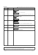
REVISIONS The manual number is given on the bottom left of the back cover. Print Date Dec., 1999 Sep., 2000 Jun., 2001 Sep., 2001 Apr., 2002 Oct., 2002 Manual Number Revision SH(NA)-080037-A First edition SH(NA)-080037-B Addition model Q33B, Q63B, Q63P Addition Section 2.3, 4.5, 11.2.3, 11.2.10, 11.2.11 Partial correction Section 1.2, 2.2, 4.1, 4.2, 5.1.1, 5.2, 8.1.5, 11.2.1, 11.3.2, 11.5.1, 11.6, 11.7 SH(NA)-080037-C Addition model Q62P, Q52B, Q55B, QC05B Addition Section 6.
INTRODUCTION Thank you for choosing the Mitsubishi MELSEC-Q Series of General Purpose Programmable Controllers. Please read this manual carefully so that equipment is used to its optimum. CONTENTS SAFETY PRECAUTIONS ............................................................................................................................A- 1 REVISIONS ..................................................................................................................................................
6.5 I/O Number Allocation ............................................................................................................................ 6- 7 6.6 Guideline for Use of Extension Base Units (Q5B) ............................................................................. 6- 8 7 MEMORY CARD AND BATTERY 7- 1 to 7- 6 7.1 Memory Card Specifications .................................................................................................................. 77.
11 TROUBLESHOOTING 11- 1 to 11-99 11.1 Troubleshooting Basics ...................................................................................................................... 11- 1 11.2 Troubleshooting.................................................................................................................................. 11- 2 11.2.1 Troubleshooting flowchart........................................................................................................... 11- 2 11.2.
(Related manual) ....................................................High Performance model QCPU (Q Mode) User's Manual (Function Explanation, Program Fundamentals) CONTENTS 1 OVERVIEW 1.1 Features 1.2 Programs 1.3 Convenient Programming Devices and Instructions 2 SYSTEM CONFIGURATION FOR SINGLE CPU SYSTEM 2.1 System Configuration 2.2 Precaution on System configuration 2.
4.8.4 Real numbers (floating decimal point data) 4.9 Character String Data 5 ASSIGNMENT OF I/O NUMBERS 5.1 Relationship Between the Number of Stages and Slots of the Extension Base Unit 5.2 Installing Extension Base Units and Setting the Number of Stages 5.3 Base Unit Assignment (Base Mode) 5.4 What are I/O Numbers? 5.5 Concept of I/O Number Assignment 5.5.1 I/O numbers of main base unit and extension base units 5.5.2 Remote station I/O number 5.6 I/O Assignment by GX Developer 5.6.
7.6 Remote Operation 7.6.1 Remote RUN/STOP 7.6.2 Remote PAUSE 7.6.3 Remote RESET 7.6.4 Remote latch clear 7.6.5 Relationship of the remote operation and High Performance model QCPU RUN/STOP switch 7.7 Changing the Input Response Speed of the Q Series Compatible Module (I/O Response Time) 7.7.1 Selecting the response time of the input module 7.7.2 Selecting the response time of the high speed input module 7.7.3 Selecting the response time of the interrupt module 7.
8 COMMUNICATION WITH INTELLIGENT FUNCTION MODULE/SPECIAL FUNCTION MODULE 8.1 Communication Between High Performance model QCPU and Q-series Intelligent Function Modules 8.1.1 Initial setting and automatic refresh setting using GX Configurator 8.1.2 Communication using device initial value 8.1.3 Communication using FROM/TO instruction 8.1.4 Communication using the intelligent function module device 8.1.5 Communication using the instructions dedicated for intelligent function modules 8.
10.5 Intelligent Function Module Devices (U \G ) 10.6 Index Registers (Z) 10.6.1 Switching between scan execution type programs and low speed execution type programs 10.6.2 Switching between scan/low speed execution programs and interrupt/fixed scan execution type programs 10.7 File Registers (R) 10.7.1 File register capacity 10.7.2 Differences in memory card access method by memory card type 10.7.3 Registering the file registers 10.7.4 File register designation method 10.7.
13 OUTLINE OF MULTIPLE CPU SYSTEMS 13.1 Features 13.2 Outline of Multiple CPU Systems 13.3 Differences with Single CPU Systems 14 SYSTEM CONFIGURATION OF MULTIPLE CPU SYSTEMS 14.1 System Configuration 14.2 Precautions During Multiple CPU System Configuration 14.2.1 Function versions of High Performance model QCPU , motion CPUs and PC CPU module that can be sued, and their mounting positions 14.2.2 Precautions when using Q series corresponding I/O modules and intelligent function modules 14.2.
18 PROCESSING TIME FOR MULTIPLE CPU SYSTEM HIGH PERFORMANCE MODEL QCPUs 18.1 Concept behind QCPU Scanning Time 18.2 Factor to Prolong the Scan Time 19 STARTING UP THE MULTIPLE CPU SYSTEM 19.1 Flow-chart for Starting Up the Multiple CPU System 19.2 Setting Up the Multiple CPU System Parameters (Multiple PLC Settings, Control PLC Settings) 19.2.1 System configuration 19.2.2 Creating new systems 19.2.
About Manuals The following manuals are related to this product. Referring to this list, please request the necessary manuals. Related Manuals Manual Number (Model Code) Manual Name High Performance model QCPU (Q Mode) User's Manual (Function Explanation, Program Fundamentals) This manual explains the functions, programming methods, devices and so on necessary to create programs with the High Performance model QCPU.
How to Use This Manual This manual is prepared for users to understand the hardware specifications of those modules such as the CPU modules, power supply modules, and base units, maintenance and inspections of the system, and troubleshooting required when you use MELSEC-Q series PLCs. The manual is classified roughly into three sections as shown below. 1) Chapters 1 and 2 Describe the outline of the CPU module and the system configuration.
About the Generic Terms and Abbreviations This manual uses the following general names and abbreviations in the descriptions of the High Performance model QCPU unless otherwise specified. Generic Term/Abbreviation High Performance model QCPU Q Series Description General name for Q02CPU, Q02HCPU, Q06HCPU, Q12HCPU, and Q25HCPU modules. Abbreviation for Mitsubishi MELSEC-Q Series Programmable Logic Controller.
1 OVERVIEW MELSEC-Q 1 OVERVIEW 1 This Manual describes the hardware specifications and handling methods of the High Performance model QCPU. The Manual also describes those items related to the specifications of the power supply module, main base unit, extension base unit, extension cable, memory card and battery. Functions are added when the High Performance model QCPU is updated. The added functions can be discriminated by the function version/serial number of the CPU module. Table 1.
1 OVERVIEW MELSEC-Q 1.1 Features 1 High Performance model QCPU has the following new features: (1) Controllable multiple I/O points All High Performance model QCPUs support 4096 points (X/Y0 to FFF) as the number of actual I/O points capable of getting access to the I/O module installed on the base unit. They also support 8192 points max.
1 OVERVIEW MELSEC-Q (6) Saved space by a reduction in size The installation space for Q series has been reduced by approx. 60 % of the space for AnS series. Comparison of installation space 1SX10 98mm (3.86 inch) 1SY50 1SX41 1SY41 1SX81 1SY81 1SX42 1SY42 PULL 5 Slot Main Base Unit 245mm(9.65inch) (depth:98mm(3.86inch)) 8 Slot Main Base Unit 328mm(12.92inch) 12 Slot Main Base Unit 439mm(17.30inch) (7) Connection of up to seven extension base units.
1 OVERVIEW MELSEC-Q (9) Data can be written automatically to standard ROM You need not use GX Developer to write parameters/programs on a memory card to the standard ROM of the High Performance model QCPU. When the standard ROM is used to perform ROM operation, you can load a memory card into the High Performance model QCPU and write parameters/programs on the memory card to the standard ROM. Hence, you need not carry GX Developer (personal computer) to rewrite the parameters/programs.
2 SYSTEM CONFIGURATION FOR SINGLE CPU SYSTEM MELSEC-Q 2 SYSTEM CONFIGURATION FOR SINGLE CPU SYSTEM This section describes the system configuration of the High Performance model QCPU, cautions on use of the system, and configured equipment. 2.1 System Configuration 2 The outline of the equipment configuration, configuration with peripheral devices, and system configuration in the High Performance model QCPU system is described below.
2 SYSTEM CONFIGURATION FOR SINGLE CPU SYSTEM MELSEC-Q (b) If the slim type main base unit (Q3SB) is used MITSUBISHI MITSUBISHI LITHIUM BATTERY Memory card *1 (Q2MEM-1MBS,Q2MEM-2MBS, Q2MEM-2MBF,Q2MEM-4MBF, Q2MEM-8MBA,Q2MEM-16MBA, Q2MEM-32MBA) High Performance model QCPU (Q02CPU,Q02HCPU,Q06HCPU, Q12HCPU,Q25HCPU) Slim type main base unit (Q32SB,Q33SB,Q35SB) *2 Battery (Q6BAT) Slim type power supply module, *3 I/O module , Intelligent function module POINTS 1: The number of memory cards to be installe
2 SYSTEM CONFIGURATION FOR SINGLE CPU SYSTEM MELSEC-Q (2) Configuration of peripheral devices MITSUBISHI Memory card 1 (Q2MEM-1MBS,Q2MEM-2MBS, Q2MEM-2MBF,Q2MEM-4MBF, Q2MEM-8MBA,Q2MEM-16MBA, Q2MEM-32MBA) High Performance model QCPU (Q02CPU,Q02HCPU,Q06HCPU, Q12HCPU,Q25HCPU) USB cable 1 (To be procured yourself) Only Q02HCPU, Q06HCPU Q12HCPU and Q25HCPU can be used.
2 SYSTEM CONFIGURATION FOR SINGLE CPU SYSTEM MELSEC-Q (3) Outline of system configuration (a) If the main base unit (Q3B) is used Extension cable 1st extension stage O U T CPU module Main base unit(Q312B) Power supply module 0 1 2 3 4 5 6 7 8 9 10 11 Slot No.
2 SYSTEM CONFIGURATION FOR SINGLE CPU SYSTEM MELSEC-Q (b) If the slim type main base unit (Q3SB) is used CPU module System configuration Power supply module Slim type main base unit (Q35SB) Slot No. 0 1 2 3 4 00 20 40 60 80 1F 3F 5F 7F 9F The above system assumes that each slot is loading with a 32-point module.
2 SYSTEM CONFIGURATION FOR SINGLE CPU SYSTEM MELSEC-Q 2.2 Precaution on System Configuration This section describes hardware and software packages compatible with QCPU. (1) Hardware (a) The number of modules to be installed and functions are limited depending on the type of the modules.
2 SYSTEM CONFIGURATION FOR SINGLE CPU SYSTEM MELSEC-Q (d) The modules shown below cannot be used.
2 SYSTEM CONFIGURATION FOR SINGLE CPU SYSTEM MELSEC-Q 2.3 Confirming the Serial Number and Function Version The CPU module serial No. can be confirmed on the rated plate and GX Developer's system monitor. (1) Confirming the serial No. on the rated plate The serial No. and function version can be confirmed on the rating plate. Serial No. (First five digits) MODEL Function version SERIAL 020920000000000-B LISTED 80M1 IND. CONT. EQ. MADE IN JAPAN (2) Confirming the serial No.
3 GENERAL SPECIFICATIONS MELSEC-Q 3 GENERAL SPECIFICATIONS Performance specification of PLC is as follows: Item Specifications Operating ambient 0 to 55°C temperature Storage ambient -25 to 75°C temperature 3 Operating ambient humidity Storage ambient humidity Conforming Vibration resistance to JIS B 3502, IEC 61131-2 Under intermittent vibration Under continuous vibration Shock resistance Operating ambience 3 5 to 95%RH 4, non-condensing 5 to 95%RH 4, non-condensing Frequency Accelerat
3 GENERAL SPECIFICATIONS MELSEC-Q MEMO 3 3-2 3-2
4 HARDWARE SPECIFICATION OF THE CPU MODULE MELSEC-Q 4 HARDWARE SPECIFICATION OF THE CPU MODULE 4.1 Performance Specification The table below shows the performance specifications of the CPU module.
4 HARDWARE SPECIFICATION OF THE CPU MODULE MELSEC-Q Performance Specifications (continued) Model Item Q02CPU Q06HCPU Remark Q12HCPU Latch relay [L] Default 8192 points (L0 to 8191) Link relay [B] Default 8192points (B0 to 1FFF) Timer [T] Retentive timer [ST] Counter [C] Default 2048 points (T0 to 2047) (for low / high speed timer) Select between low / high speed timer by instructions. The measurement unit of the low / high speed timer is set with parameters.
4 HARDWARE SPECIFICATION OF THE CPU MODULE MELSEC-Q Performance Specifications (continued) Model Item Q02CPU Q02HCPU Q12HCPU Link special relay [SB] 2048 points (SB0 to 7FF) Link special register [SW] 2048 points (SW0 to 7FF) Step relay [S] 8192 points (S0 to 8191) Index register [Z] Number of device points Remark Q06HCPU Q25HCPU 16 points (Z0 to 15) 4096 points (P0 to 4095), set parameter values to select usable range Pointer [P] of in-file pointer / shared pointers.
4 HARDWARE SPECIFICATION OF THE CPU MODULE MELSEC-Q 4.2 Part Names and Settings This section explains the part names and settings of the module. With front cover open Front face 1) Q02HCPU 2) MODE RUN ERR. USER BAT. BOOT 9) 3) 4) MODE RUN ERR. USER BAT. BOOT ON SW 5) 6) 10) 7) 1 2 3 4 5 13) STOP RUN 14) RESET L CLR 15) PULL USB 11) 1 12) RS-232 8) When opening the front cover, put your finger here. Side face 16) 17) 19) 18) 1: Not provided for Q02CPU.
4 HARDWARE SPECIFICATION OF THE CPU MODULE No. Name 1) Module fixing hook 2) "Mode" LED 3) "RUN" LED 4) "ERR." LED 5) "USER" LED 6) "BAT." LED 7) "BOOT" LED 8) Module loading lever 4-5 MELSEC-Q Application Hook used to fix the module to the base unit. (Single-motion installation) Indicates the mode of the CPU module. ON (green) : Q mode ON (orange) : A mode Flicker (green) : Enforced ON/OFF for external I/O registered Indicates the operating status of the CPU module.
4 HARDWARE SPECIFICATION OF THE CPU MODULE MELSEC-Q No. Name Application 9) Memory card EJECT button Used to eject the memory card from the CPU module. Memory card loading Connector used to load the memory card to the CPU module. 10) connector Connector for connection with USB-compatible peripheral device. (Connector type B) 11) USB connector 1 Can be connected by USB-dedicated cable. Not available for Q02CPU.
4 HARDWARE SPECIFICATION OF THE CPU MODULE MELSEC-Q 4.3 Switch Operation After Writing in Program When writing a program into the CPU module, do not turn off the system protect set switch SW1 in advance (When the switch is turned off, the system will not be protected). (1) When a program is written while CPU module is stopped: When a program is written while the CPU module is stopped, operate the switch in the order shown below.
4 HARDWARE SPECIFICATION OF THE CPU MODULE MELSEC-Q 4.4 Latch Clear Operation To perform latch clear, operate the RESET/L.CLR switch in the following procedure. 1) RUN/STOP switch : STOP 2) RESET/L.CLR switch : Move the switch to L.CLR several times until the USER LED flickers. "USER" LED: Flicker Ready for latch clear. 3) RESET/L.CLR switch : Move the switch to L.CLR once more. "USER" LED: OFF Latch clear complete.
4 HARDWARE SPECIFICATION OF THE CPU MODULE (b) (c) 4-9 MELSEC-Q Operations with CPU module (automatic write to standard ROM) 1) Switch OFF the power supply to the PLC. 2) Mount the memory card that contains the parameters and programs to be booted onto the CPU module. 3) Set the parameter's valid drive in the mounted memory card with the CPU module's dip switches.
5 POWER SUPPLY MODULE MELSEC-Q 5 POWER SUPPLY MODULE 5.1 Specification 5.1.1 Power supply module specifications This section gives the specifications of the power supply modules. Item Performance Specifications Q61P-A2 Q62P Power supply module loading slot Q3B, Q6B Q61P-A1 Base loading position Applicable base unit Input power supply 100 to 120VAC +10% +10% +10% 200 to 240VAC 100 to 240VAC -15% -15% -15% (85 to 132VAC) Input frequency Input voltage distortion factor Max. input apparent power Max.
5 POWER SUPPLY MODULE MELSEC-Q Power Supply Module Specifications (Continued) Performance Specifications Item Q64P Base loading position Power supply module loading slot Applicable base unit Q3B, Q6B 100 to 120VAC/200 to 240VAC Input power supply +10% -15% (85V to 132VAC/170 to 264VAC) Input frequency 50/60Hz ±5% Input voltage distortion factor Within 5% (refer to section 5.1.3) Max. input apparent power Inrush current 5 160VA 20A within 8ms Rated output current 5VDC 24VDC 8.
5 POWER SUPPLY MODULE MELSEC-Q Performance Specifications Item Q61SP Base loading position Slim type power supply module loading slot Applicable base unit Q3SB 100 to 240VAC Input power supply +10% -15% (85 to 264VAC) Input frequency 50/60Hz ±5% Input voltage distortion factor Within 5% (refer to section 4.3.1) Max. input apparent power Inrush current 40VA 20A within 8ms Rated output current 5VDC 2A 24VDC —— Overcurrent protection*1 5VDC 2.
5 POWER SUPPLY MODULE MELSEC-Q Power Supply Module Specifications (Continued) Performance Specifications Item A1S61PN Base loading position A1S62PN Applicable base unit QA1S65B, QA1S68B +10% 100 to 240VAC -15% (85 to 264VAC) Input power supply Input frequency 50/60Hz ±5% Within 5% Max. input apparent power Max. input power Inrush current Overcurrent protection 1 Overvoltage protection 2 +30% -35% (15.6 to 31.
5 POWER SUPPLY MODULE MELSEC-Q POINTS 1 : Overcurrent protection The overcurrent protection device shuts off the 5 V, 24 VDC circuit and stops the system if the current flowing in the circuit exceeds the specified value. The LED of the power supply module is unlit or lit dimly upon a voltage drop. If this device is activated, switch the input power supply off and eliminate the cause such as insufficient current capacity or short. Then, a few minutes later, switch it on to restart the system.
5 POWER SUPPLY MODULE MELSEC-Q 5.1.2 Selecting the power supply module The power supply module is selected according to the total of current consumption of the base units, I/O modules, intelligent function module, special function module, and peripheral devices supplied by its power supply module. For the internal current consumption of 5 VDC of the base unit, refer to Chapter 6.
5 POWER SUPPLY MODULE MELSEC-Q (b) Ideas for reducing voltage drops The following methods are effective to reduce voltage drops at the extension cables. 1) Changing the module loading positions Load large current consumption modules on the main base unit. Load small current consumption modules on the extension base unit. 2) Using short extension cables The shorter the extension cable is, the smaller the resistance and voltage drops are. Use the shortest possible extension cables.
5 POWER SUPPLY MODULE MELSEC-Q (3) When the base unit is of QA1S6B: Power supply module A1S61PN, A1S62PN, A1S63P Base unit QA1S65B and QA1S68B I/O module A1SX10, A1SY10, etc. Special function module A1SD61, A1SD75P1-S3, etc. peripheral devices 2 AD75TU 2: Select the power supply module also in consideration of the current consumption of the peripheral devices connected to the special function module.
5 POWER SUPPLY MODULE MELSEC-Q 5.2 Names of Parts and Settings The names of the parts of each power supply module are described below. (1) Q61P-A1, Q61P-A2, Q62P, Q63P, Q64P, Q61SP 1) 8) Q61P-A2 7) POWER 1) 8) 7) POWER INPUT INPUT 200-240VAC 100-120VAC 50/60Hz 105VA OUTPUT 5VDC 6A 50/60Hz 105VA OUTPUT 5VDC 6A L 24VDC 0.5A + - ERR. 2) + ERR. L 24VDC 0.
5 POWER SUPPLY MODULE No. 1) Name MELSEC-Q Application POWER LED 5VDC power indicator LED 1) Turned ON when the whole system operates normally. 2) Turned OFF (opened) when a stop error occurs in the CPU module. 2) ERR terminals 3) In a multiple CPU system configuration, turned OFF when a stop error occurs in any of the CPU modules. Normally off when loaded in an extension base unit. 3) FG terminal Ground terminal connected to the shield pattern of the printed circuit board.
5 POWER SUPPLY MODULE MELSEC-Q (2) A1S61PN, A1S62PN and A1S63P 9) 9) MELSECA1S61PN MELSECA1S62PN 1) POWER MELSECA1S63P 1) POWER MITSUBISHI INPUT 100-240VAC 105VA 50 / 60Hz 9) MITSUBISHI 8) OUTPUT 5VDC 5A INPUT 100-240VAC 105VA 50 / 60Hz 1) POWER MITSUBISHI 8) OUTPUT 5VDC 3A 24VDC 0.6A INPUT DC15.6 31.2V 8) OUTPUT DC 5V 5A NC +24V NC NC 24G NC FG (FG) (FG) NC NC (LG) (LG) LG INPUT INPUT 100-240VAC 100-240VAC A1S61PN 3) 4) 5) 7) No.
6 BASE UNIT AND EXTENSION CABLE MELSEC-Q 6 BASE UNIT AND EXTENSION CABLE This section describes the specifications of the extension cables for the base units (main, slim type and extension base unit) used in the PLC system and the specification standards of the extension base unit. 6.
6 BASE UNIT AND EXTENSION CABLE MELSEC-Q (3) Extension base unit specifications (Type not requiring power supply module) Type Item Q52B Q55B 2 5 Number of I/O modules installed Possibility of extension Extendable Applicable module Q series modules 5 VDC internal current consumption Mounting hole size 0.080A 0.100A M4 screw hole or H External dimensions 4.5 hole (for M4 screw) 98mm (3.86inch) W 106mm (4.17inch) 189mm (7.44inch) D 44.1mm (1.74inch) Weight 0.14kg Attachment 0.
6 BASE UNIT AND EXTENSION CABLE MELSEC-Q 6.2 Extension Cable Specification Table The list below shows the specifications of the extension cables which can be used for the High Performance model QCPU system. Type QC05B QC06B QC12B QC30B Cable length 0.45m (1.48ft.) 0.6m (1.97ft.) 1.2m (3.93ft.) 3.0m (9.84ft.) Application Connection across the main base unit and extension base unit or across the extension base units. Item Weight 0.15 kg 0.16 kg 0.22 kg QC50B QC100B 5.0m (16.39ft.) 10.
6 BASE UNIT AND EXTENSION CABLE MELSEC-Q (2) Slim type main base unit(Q32SB, Q33SB, Q35SB) 2) 3) 5V 5V 56 SG POWER CPU I/O0 I/O1 I/O2 4) No. Name I/O3 I/O4 1) Application Connector for installing the power supply module, CPU module, I/O modules, and 1) Module connector intelligent function module. To the connectors located in the spare space where these modules are not installed, attach the supplied connector cover or the blank cover module (QG60) to prevent entry of dirt.
6 BASE UNIT AND EXTENSION CABLE MELSEC-Q (3) Extension base unit (Q5 B, Q6 B, QA1S6 B) Q52B, Q55B 5) 6) IN OUT 3) 2) I/O0 I/O1 I/O2 I/O3 I/O4 I/05 I/06 1) 7) 4) Q63B,Q65B, Q68B, Q612B 5) 6) IN 3) OUT 5V 2) 56 POWER I/00 I/01 I/02 I/03 I/04 I/07 I/08 I/09 I/10 I/11 1) 4) 7) QA1S65B, QA1S68B 5) 6) 3) IN OUT 5V 2) SG FG POWER I/O0 I/O1 I/O2 I/O3 I/O4 I/O5 I/O6 I/O7 QA1S68B 1) 4) No.
6 BASE UNIT AND EXTENSION CABLE MELSEC-Q 6.4 Setting the Extension Base Unit The number of stages setting method of each extension base unit to be used when extension base units are installed is described below. OUT IN PIN1 1 2 3 4 5 6 7 Stage No. setting connector Setting of Stage Number for Extension Base Units Number Setting for Extension Stages 1st stage 2nd stage 3rd stage 4th stage 5th stage 6th stage 7th stage Setting of stage No. setting connector POINTS To set the stages No.
6 BASE UNIT AND EXTENSION CABLE MELSEC-Q 6.5 I/O Number Allocation 2nd extension stage 3rd extension stage I N O U T I N O U T Power supply module O U T Power supply module 1st extension stage I N Power supply module CPU module O U T Power supply module The I/O numbers are automatically allocated in the system loading status.
6 BASE UNIT AND EXTENSION CABLE MELSEC-Q 6.6 Guideline for Use of Extension Base Units (Q5B) Since the Q5B is supplied with 5VDC from the power supply module on the main base unit, a voltage drop occurs at extension cables. Improper I/O may be provided if the specified voltage (4.75VDC or higher) is not supplied to the "IN" connector of the Q5B. When using the Q5B, make sure that the "IN" connector of the Q5B is supplied with 4.75VDC or higher.
6 BASE UNIT AND EXTENSION CABLE MELSEC-Q List for Calculating Voltage Drops Occurring at Extension Cables in System Consisting of Extensions 1 to 7 Q5B Loading Position Extension stage 1 Extension stage 2 Extension stage 3 Extension stage 4 Extension stage 5 Extension stage 6 Extension stage 7 V2 V3 V4 V5 V6 V7 Sum Total of Voltage Drops to "IN" Connector of Q5B (V) ---- ---- ---- ---- ---- ---- V=V1 ---- ---- ---- ---- ---- V=V1+V2 ---- ---- ---- ---- V=V1+V2+V3 ---- ---- --
6 BASE UNIT AND EXTENSION CABLE MELSEC-Q List for Calculating Voltage Drops Occurring at Extension Cables when connecting Q6B between Q3B and Q5B Position of extension base unit Voltage drop caused by extension cable from the main base unit to the Q5B IN connector (V) Q6B Q5B Extension stage 1 Extension stage 2 V=(R1+R2)I1 Extension stage 3 V=(R1+R2+R3)I1 Extension stage 1 to 3 Extension stage 4 V=(R1+R2+R3+R4)I1 Extension stage 1 to 4 Extension stage 5 V=(R1+R2+R3+R4+R5)I1 Extension
6 BASE UNIT AND EXTENSION CABLE MELSEC-Q POINT When connecting GOT by extension cable that is 13.2 m (43.31ft) or longer, the bus extension connector box A9GT-QCNB is required. Since the A9GT-QCNB is supplied with 5VDC from the power supply module loaded on the main base unit, 29mA must be added to "Im" as the current consumption of the A9GT-QCNB. For details of the GOT-bus connection, refer to the GOT-A900 Series User's Manual (Connection).
7 MEMORY CARD AND BATTERY MELSEC-Q 7 MEMORY CARD AND BATTERY This section describes the specifications and handling of the memory card and battery which can be used on the High Performance model QCPU. The memory card is necessary for sampling tracing. The memory card is also used to handle file registers of more than the number of points that can be stored in the standard RAM. (Refer to Section 4.1) 7.
7 MEMORY CARD AND BATTERY MELSEC-Q 7.2 Battery Specifications (For CPU Module and SRAM Card) (1) For CPU module Type Q6BAT Item Manganese dioxide lithium primary Classification battery Initial voltage 3.0V Nominal current 1800mAh Storage life 10 years (room temperature) Total power failure time Refer to Section 10.3.1.
7 MEMORY CARD AND BATTERY MELSEC-Q 7.3 Handling the Memory Card (1) Formatting of memory card Any SRAM or ATA card must have been formatted to use on the High Performance model QCPU. Since the SRAM or ATA card purchased is not yet formatted, format it using GX Developer before use. (The Flash card need not be formatted.) For the formatting procedure, refer to the Operating Manual of the GX Developer.
7 MEMORY CARD AND BATTERY MELSEC-Q 7.4 The Names of The Parts of The Memory Card The names of the parts of the memory card are described below. 1) 3) 4) Write-protected ON "RELEASE" direction "LOCK" direction 2) No.
7 MEMORY CARD AND BATTERY MELSEC-Q 7.5 Memory Card Loading/Unloading Procedures (1) To install the memory card Install the memory card into the CPU module, while paying attention to the orientation of the memory card. Insert the memory card securely into the connector until the height of the memory card reaches that of the memory card EJECT button. Memory card EJECT button CPU module Memory card Insert it in this direction.
7 MEMORY CARD AND BATTERY MELSEC-Q 7.6 Installation of Battery (for CPU Module and Memory Card) (1) The battery for the CPU module is shipped with its connector disconnected. Connect the connector as follows. Refer to Section 10.3 for the service life of the battery and how to replace the battery. Open the cover at the CPU module's bottom. Side of the CPU module Confirm that the battery is loaded correctly. Front Insert the battery connector into the connector pin on the case.
8 EMC AND LOW VOLTAGE DIRECTIVE MELSEC-Q 8 EMC AND LOW VOLTAGE DIRECTIVE For the products sold in European countries, the conformance to the EMC Directive, which is one of the European Directive, has been a legal obligation since 1996. Also, conformance to the Low Voltage Directive, another European Directive, has been a legal obligation since 1997.
8 EMC AND LOW VOLTAGE DIRECTIVE MELSEC-Q 8.1.2 Installation instructions for EMC Directive The PLC is open equipment and must be installed within a control cabinet for use. This not only ensures safety but also ensures effective shielding of PLC-generated electromagnetic noise. (1) Control cabinet (a) Use a conductive control cabinet. (b) When attaching the control cabinet's top plate or base plate, mask painting and weld so that good surface contact can be made between the cabinet and plate.
8 EMC AND LOW VOLTAGE DIRECTIVE MELSEC-Q 8.1.3 Cables The cables extracted from the control panel contain a high frequency noise component. On the outside of the control panel, therefore, they serve as antennas to emit noise. To prevent noise emission, use shielded cable for the cables which are connected to the I/O modules and intelligent function modules and may be extracted to the outside of the control panel. The use of a shielded cable also increases noise resistance.
8 EMC AND LOW VOLTAGE DIRECTIVE MELSEC-Q (2) MELSECNET/H module Always use a double-shielded coaxial cable (MITSUBISHI CABLE INDUSTRIES, LTD.: 5C-2V-CCY) for the coaxial cables MELSECNET/H module. Radiated noise in the range of 30MHz or higher can be suppressed by use of the doubleshielded coaxial cables. Earth the double-shielded coaxial cable by connecting its outer shield to the ground. Shield Earth here Refer to (1) for the earthing of the shield.
8 EMC AND LOW VOLTAGE DIRECTIVE MELSEC-Q 8.1.4 Power supply module Always ground the LG and FG terminals after short-circuiting them. 8.1.5 When using QA1S6 B type base unit (1) Cable (a) Earthing of shielded cable • Earth the shield of the shielded cable as near the unit as possible taking care so that the earthed cables are not induced electromagnetically by the cable to be earthed.
8 EMC AND LOW VOLTAGE DIRECTIVE MELSEC-Q (b) Positioning modules External wiring connector A1SD75 module Power supply module Precautions to be followed when the machinery conforming to the EMC Directive is configured using the A1SD75P1-S3/A1SD75P2-S3/A1SD75P3S3 (hereafter referred to as the A1SD75) are described below. 1) When wiring with a 2 m (6.56 ft.) or less cable • Ground the shield section of the external wiring cable with the cable clamp.
8 EMC AND LOW VOLTAGE DIRECTIVE MELSEC-Q (c) CC-Link module 1) Be sure to ground the cable shield that is connected to the CC-Link module close to the exit of control panel or to any of the CC-Link stations within 30 cm (11.81 inch) from the module or stations. The CC-Link dedicated cable is a shielded cable. As shown in the illustration below, remove a portion of the outer covering and ground as large a surface area of the exposed shield part as possible.
8 EMC AND LOW VOLTAGE DIRECTIVE MELSEC-Q 8.1.6 Others (1) Ferrite core A ferrite core has the effect of reducing radiated noise in the 30MHz to 100MHz band. It is not required to fit ferrite cores to cables, but it is recommended to fit ferrite cores if shield cables pulled out of the enclosure do not provide sufficient shielding effects. It should be noted that the ferrite cores should be fitted to the cables in the position immediately before they are pulled out of the enclosure.
8 EMC AND LOW VOLTAGE DIRECTIVE MELSEC-Q 8.2 Requirement to Conform to the Low Voltage Directive The Low Voltage Directive requires each device that operates with the power supply ranging from 50 to 1000VAC and 75 to 1500VDC to satisfy the safety requirements. In Sections 8.2.1 to 8.2.6, cautions on installation and wiring of the MELSEC-Q series PLC to conform to the Low Voltage Directive are described.
8 EMC AND LOW VOLTAGE DIRECTIVE MELSEC-Q 8.2.3 Power supply The insulation specification of the power supply module was designed assuming installation category II. Be sure to use the installation category II power supply to the PLC. The installation category indicates the durability level against surge voltage generated by a thunderbolt. Category I has the lowest durability; category IV has the highest durability. Category IV Category III Category II Category I Figure 8.
8 EMC AND LOW VOLTAGE DIRECTIVE MELSEC-Q 8.2.5 Grounding There are the following two different grounding terminals. Use either grounding terminal in an earthed status. Protective grounding : Maintains the safety of the PLC and improves the noise resistance. Functional grounding : Improves the noise resistance. 8.2.
9 LOADING AND INSTALLATION MELSEC-Q 9 LOADING AND INSTALLATION In order to increase the reliability of the system and exploit the maximum performance of its functions, this section describes the methods and precautions for the mounting and installation of the system. 9.1 General Safety Requirements ! DANGER Install a safety circuit external to the PLC that keeps the entire system safe even when there are problems with the external power supply or the PLC module.
9 LOADING AND INSTALLATION MELSEC-Q ! DANGER When connecting a peripheral device to the CPU module or connecting a personal computer or the like to the special function module to exercise control (data change) on the running PLC, configure up an interlock circuit in the sequence program to ensure that the whole system will always operate safely.
9 LOADING AND INSTALLATION MELSEC-Q (1) System design circuit example (when not using ERR contact of power supply module) POWER SUPPLY FOR AC POWER SUPPLY Input switched when power supply established.
9 LOADING AND INSTALLATION MELSEC-Q (2) System design circuit example (when using ERR contact of power supply module) POWER SUPPLY FOR AC/DC TRANSFORMER TRANSFORMER Input switched when power supply established. FUSE FUSE CPU MODULE SM52 RUN/STOP circuit interlocked with RA1 (run monitor relay) SM403 XM NO DC POWER SUPPLY Ym (-) (+) Yn FUSE Set time for DC power supply to be established.
9 LOADING AND INSTALLATION MELSEC-Q (3) Fail-safe measures against failure of the PLC Vacant Output 16 points Y80 to Y8F Output 16 points Output 16 points Output 16 points Power supply module Output 16 points Input 16 points Input 16 points Input 16 points Input 16 points CPU module Power supply module Failure of a CPU module or memory can be detected by the self-diagnosis function. However, failure of I/O control area may not be detected by the CPU module.
9 LOADING AND INSTALLATION MELSEC-Q 9.2 Calculating Heat Generation by PLC The ambient temperature inside the board storing the PLC must be suppressed to a PLC usable ambient temperature of 55°C. For the design of radiation from the storing board, it is necessary to know the average power consumption (heating value) of the devices and instruments stored in the board. Here the method of obtaining the average power consumption of the PLC system is described.
9 LOADING AND INSTALLATION MELSEC-Q (6) Power consumption of the power supply section of the intelligent function module W S = I5V 5 + I24V 24 + I100V 100 (W) The total of the power consumption values calculated for each block becomes the power consumption of the overall sequencer system. W = W PW + W 5V + W 24V + W OUT + W IN + W S (W) From this overall power consumption (W), calculate the heating value and a rise in ambient temperature inside the board.
9 LOADING AND INSTALLATION MELSEC-Q (f) Average power consumption due to voltage drop in the output section of the output module W OUT = 0 (W) (g) Average power consumption of the input section of the input module W IN = 0.004 24 32 1 = 3.07 (W) (h) Power consumption of the power supply section of the intelligent function module W S = 0 (W) (i) Power consumption of overall system. W = 3.84 + 8.97 + 0 + 0 + 3.07 + 0 = 15.
9 LOADING AND INSTALLATION MELSEC-Q 9.3 Module Installation 9.3.1 Precaution on installation ! CAUTION Use the PLC in an environment that meets the general specifications contained in this manual. Using this PLC in an environment outside the range of the general specifications could result in electric shock, fire, erroneous operation, and damage to or deterioration of the product.
9 LOADING AND INSTALLATION MELSEC-Q (6) Install the main base unit (by screwing) in the following procedure. 1) Fit the two base unit top mounting screws into the enclosure. Panel 2) Place the right-hand side notch of the base unit onto the right-hand side screw. Panel 3) Place the left-hand side pear-shaped hole onto the left-hand side screw. Panel 4) Fit the mounting screws into the mounting screw holes in the base unit bottom and retighten the four mounting screws.
9 LOADING AND INSTALLATION MELSEC-Q (7) Note the following points when mounting a DIN rail. Mounting a DIN rail needs special adaptors (optional), which are to be userprepared. (a) Applicable adaptor types For Q38B, Q312B, Q68B, Q612B : Q6DIN1 For Q35B, Q65B : Q6DIN2 For Q33B, Q52B, Q55B, Q63B, Q32SB, Q33SB, Q35SB : Q6DIN3 (b) Adaptor installation method The way to install the adaptors for mounting a DIN rail to the base unit is given below.
9 LOADING AND INSTALLATION MELSEC-Q 9.3.2 Instructions for mounting the base unit When mounting the PLC to an enclosure or similar, fully consider its operability, maintainability and environmental resistance. (1) Module mounting position For enhanced ventilation and ease of module replacement, leave the following clearances between the module top/bottom and structure/parts. (a) In case of main base unit or extension base unit Indicates the panel top, wiring duct or any part position. 30mm (1.
9 LOADING AND INSTALLATION MELSEC-Q (b) In case of slim type main base unit Indicates the panel top, wiring duct or any part position. 30 mm (1.18 inch) or more 1 PLC Door Panel 30 mm (1.18 inch) or more 17 mm (0.67 inch) or more 2 20 mm (0.79 inch) or more 3 5 mm (0.20 inch) or more 1 : For wiring duct with 50 (1.97 inch) mm or less height. 40 mm (1.58 inch) or more for other cases.
9 LOADING AND INSTALLATION MELSEC-Q (2) Module mounting orientation (a) Since the PLC generates heat, it should be mounted on a well ventilated location in the orientation shown below. (b) Do not mount it in either of the orientations shown below. Vertical Flat (3) Installation surface Mount the base unit on a flat surface. If the mounting surface is not even, this may strain the printed circuit boards and cause malfunctions.
9 LOADING AND INSTALLATION MELSEC-Q 9.3.3 Installation and removal of module This section explains how to install and remove a power supply, CPU, I/O, intelligent function or another module to and from the base unit. (1) Installation and removal of the module from Q3 B, ,Q5 B and Q6 B The installation and removal of the module from Q3 B/Q6 B base unit are described below.
9 LOADING AND INSTALLATION MELSEC-Q (b) Removal from Q3 B, Q5 B and Q6 B Base unit Hold the module with both hands, and push the unit fixing hook on the top of the module with a finger until it stops. Module connector Module While pushing the unit fixing hook, and using the bottom of the module as a support, pull the module toward you. Module fixing hole Lift the module upwards and remove the module fixing latch from the module fixing hole.
9 LOADING AND INSTALLATION MELSEC-Q (2) Installation and removal of the module from QA1S6 B The procedure for installing and removing the module from the QA1S6 B base unit is described below. (a) Installation of module on QA1S6 B Insert the module fixing projections into the module fixing hole in the base unit. Base unit Module Module connector Install the module onto the base unit by pushing the top forward.
9 LOADING AND INSTALLATION MELSEC-Q (b) Removal from QA1S6 B Remove the module mounting screw, and using the bottom of the module as a support, pull the top of the module toward you. Lift the module upwards and remove the module fixing projections from the module fixing hole. Base unit Module connector Module Module fixing hole Completion POINT To remove the module, make sure to remove the module fixing screws, and then disengage the module fixing projection from the module fixing hole.
9 LOADING AND INSTALLATION MELSEC-Q 9.4 How to Set Stage Numbers for the Extension Base Unit When using two or more extension base units, their stage numbers must be set with their stage number setting connectors. Extension 1 need not be set since the extension number is factory-set to 1. Make this setting in the following procedure. (1) The stage number setting connector of the extension base unit is located under the IN side base cover. (Refer to Section 6.
9 LOADING AND INSTALLATION MELSEC-Q 9.5 Connection and Disconnection of Extension Cable (1) Instructions for handling an extension cable • Do not stamp an extension cable. • An extension cable must be connected to the base unit when the base cover has been installed. (After you have set the extension number to the extension base unit, reinstall and screw the base cover.) • When running an extension cable, the minimum bending radius of the cable should be 55mm (2.17 inch) or more.
9 LOADING AND INSTALLATION MELSEC-Q (a) To connect an extension cable to the main base unit, remove the portion under the OUT characters on the base cover with a tool such as a flat-blade screwdriver (5.5 75, 6 100). This also applies to a case where an extension cable is connected to the OUT side connector of the extension base unit.
9 LOADING AND INSTALLATION MELSEC-Q (3) Disconnection of extension cable When unplugging the extension cable, hold and pull the connector part of the extension cable after making sure that the fixing screws have been removed completely.
9 LOADING AND INSTALLATION MELSEC-Q 9.6 Wiring 9.6.1 The precautions on the wiring ! DANGER Completely turn off the external power supply when installing or placing wiring. Not completely turning off all power could result in electric shock or damage to the product. When turning on the power supply or operating the module after installation or wiring work, be sure that the module's terminal covers are correctly attached. Not attaching the terminal cover could result in electric shock.
9 LOADING AND INSTALLATION MELSEC-Q I/O module Power supply module Power supply module 24VDC I/O module 24VDC Power supply module (b) Do not connect the 24VDC outputs of two or more power supply modules in parallel to supply power to one I/O module. Parallel connection will damage the power supply modules. 24VDC External power supply (c) 100VAC, 200VAC and 24VDC wires should be twisted as dense as possible. Connect the modules with the shortest distance.
9 LOADING AND INSTALLATION MELSEC-Q (2) Wiring of I/O equipment (a) Insulation-sleeved crimping terminals cannot be used with the terminal block. It is recommended to cover the wire connections of the crimping terminals with mark or insulation tubes. (b) The wires used for connection to the terminal block should be 0.3 to 0.75mm in core and 2.8mm (0.11 inch) max. in outside diameter. 2 (c) Run the input and output lines away from each other.
9 LOADING AND INSTALLATION MELSEC-Q 9.6.2 Connecting to the power supply module The following diagram shows the wiring example of power lines, grounding lines, etc. to the main and extension base units. 100/110VAC AC Main base unit (Q38B) Q61P-A1 CPU module Fuse AC DC ERR FG LG INPUT 100-120VAC 24VDC Connect to 24VDC terminals of I/O module that requires 24VDC internally.
10 MAINTENANCE AND INSPECTION MELSEC-Q 10 MAINTENANCE AND INSPECTION ! DANGER Do not touch the terminals while power is on. Doing so could cause shock. Correctly connect the battery. Also, do not charge, disassemble, heat, place in fire, short circuit, or solder the battery. Mishandling of a battery can cause overheating or cracks which could result in injury and fires. Turn the power off when cleaning the module or tightening the terminal screws or module mounting screws.
10 MAINTENANCE AND INSPECTION MELSEC-Q 10.1 Daily Inspection The items that must be inspected daily are listed below. Daily inspection 1 2 3 4 Inspection Item Inspection Check that fixing screws Installation of base unit are not loose and the cover is not dislocated. Check that the module is Installation of I/O not dislocated and the unit module fixing hook is engaged securely. Check for loose terminal screws. Check distance between Connecting conditions Solderless terminals.
10 MAINTENANCE AND INSPECTION MELSEC-Q 10.2 Periodic Inspection The items that must be inspected one or two times every 6 months to 1 year are listed below. When the equipment is moved or modified, or layout of the wiring is changed, also perform this inspection. Periodic Inspection 1 2 Inspection Item Ambient environment Item Ambient temperature Ambient humidity Power voltage 5 Installation Connection 4 Measure with a thermometer and a hygrometer. Measure corrosive gas.
10 MAINTENANCE AND INSPECTION MELSEC-Q 10.3 Battery Replacement When the voltage of the program and power interrupt hold-on function backup battery is lowered, the special relays SM51 and SM52 are energized. Even if these special relays are energized, the contents of the program and power interrupt hold-on function are not erased immediately. If the energization of these relays is recognized, however, these contents may be deleted unintentionally.
10 MAINTENANCE AND INSPECTION MELSEC-Q 10.3.1 Battery life (1) CPU module battery (Q6BAT) life (a) The CPU module battery life is given below.
10 MAINTENANCE AND INSPECTION MELSEC-Q (b) CPU module whose serial number's first 5 digits are "04011" or earlier Battery life Energization Time Ratio SRAM card Guaranteed value (MIN) Value in actual use (TYP) After SM51 is energized (Guaranteed time after alarm occurrence) 0% 690hr 6336hr 8hr 100% 11784hr 13872hr 8hr 1 Q2MEM-1MBS Manufacturing control number " A" 2 Q2MEM-2MBS 1: The energization time ratio denotes the ratio of power-on time in a day (24 hours) .
10 MAINTENANCE AND INSPECTION MELSEC-Q 10.3.2 Battery replacement procedure (1) CPU module battery replacement procedure When the CPU module battery has been exhausted, replace the battery with a new one according to the procedure shown below. The PLC power must be on for 10 minutes or longer before dismounting the battery. Even when the battery is dismounted, the memories are backed up by the capacitor for a while.
10 MAINTENANCE AND INSPECTION MELSEC-Q (2) SRAM card CPU module battery replacement procedure Replace the SRAM card battery in the following procedure. POINTS Replace the battery while paying attention to the following. (a) To back up the data, replace the SRAM card battery with the PLC power supply ON and the SRAM card installed. (b) Start replacement after backing up the CPU module data using GX Developer.
11 TROUBLESHOOTING MELSEC-Q 11 TROUBLESHOOTING 11 This section describes the various types of trouble that occur when the system is operated, and causes and remedies of these troubles. 11.1 Troubleshooting Basics In order to increase the reliability of the system, not only highly reliable devices are used but also the speedy startup of the system after the occurrence of trouble becomes an important factor.
11 TROUBLESHOOTING MELSEC-Q 11.2 Troubleshooting The trouble investigating methods, contents of troubles for the error codes, and remedies of the troubles are described below. 11.2.1 Troubleshooting flowchart The following shows the contents of the troubles classified into a variety of groups according to the types of events. Error-occurrence description "MODE" LED off "MODE" LED flickering Proceed to Section 11.2.3, "Flowchart for when the "MODE" LED is flickering.
11 TROUBLESHOOTING MELSEC-Q 11.2.2 Flowchart for when the "MODE" LED is not turned on The following shows the flowchart to be followed when the "MODE" LED of the CPU module does not turn on at PLC power-on. "MODE" LED is not turned on. Is the power supply for all the power supply modules turned on? Is the wiring of the power supply module correct? NO YES Is the "POWER" LED for the power supply module turned on? Check the wire and turn on the power supply.
11 TROUBLESHOOTING MELSEC-Q 11.2.3 Flowchart for when the "MODE" LED is flickering The following shows the flowchart to be followed when the "MODE" LED of the CPU module flickers at PLC power-on, at operation start or during operation. "MODE" LED is flickering Did you make forced ON/OFF setting? NO Is the RESET/L.CLR switch of the CPU module in the neutral position? Neutral position Hardware fault Check operations in the order starting from the minimum system.
11 TROUBLESHOOTING MELSEC-Q 11.2.4 Flowchart for when the "POWER" LED is turned off The following shows the flowchart to be followed when the "POWER" LED of the power supply module turns off at PLC power-on or during operation. "POWER" LED is turned off. Is there a power supply? NO Supply power. YES NO Is the power supply voltage within the voltage range given in the specifications? NO YES Is the power supply module fixed? The supply voltage should be within the rated range.
11 TROUBLESHOOTING MELSEC-Q 11.2.5 Flowchart for when the "RUN" LED is turned off The following shows the flowchart to be followed when the "RUN" LED of the CPU module turns off during PLC operation. "RUN" LED is turned off. Is the "POWER" LED of the power supply module lit? Proceed to Section 11.2.4, "Flowchart for when the "POWER" LED is turned off." NO YES Is "ERR." LED on/flickering? Proceed to Section 11.2.7, "Flowchart for when the "ERR." LED is on/flickering.
11 TROUBLESHOOTING MELSEC-Q 11.2.6 When the "RUN" LED is flickering If the "RUN" LED flickers, follow the steps below. The High Performance model QCPU flickers the "RUN" LED when the RUN/STOP switch is set from STOP to RUN after the programs or parameters are written in the CPU module during the stoppage. Though this is not the trouble with the CPU module, the operation of the CPU module is stopped. To bring the CPU module into RUN status, reset the CPU module with the RESET/L.
11 TROUBLESHOOTING MELSEC-Q 11.2.8 When the "USER" LED is turned on If the "USER" LED turns on, follow the steps described below. The "USER" LED turns on when an error is detected by the CHK instruction or the annunciator (F) turns on. If the "USER" LED is on, monitor the special relays SM62 and SM80 in the monitor mode of GX Developer. • When M62 has turned ON The annunciator (F) is ON. Using SD62 to SD79, check the error cause.
11 TROUBLESHOOTING MELSEC-Q 11.2.10 Flowchart for when the "BOOT" LED is flickering The following shows the flowchart to be followed when the "BOOT" LED of the CPU module flickers at PLC power-on, at operation start or during operation. "BOOT" LED flickering Power off the PLC. Remove the memory card. Move the DIP switches SW2 and SW3 of the CPU module to ON. Power on the PLC. Is the "BOOT" LED turned on? NO CPU module hardware fault.
11 TROUBLESHOOTING MELSEC-Q 11.2.11 Flowchart for when output module LED is not turned on The following shows the flowchart to be followed when the output module LED does not turn on during PLC operation. Output module LED not turned on NO (Flickering) Is the "MODE" LED on? Refer to Section 11.2.3. YES Is the LED on when it is monitored on GX Developer? NO Reexamine the program. YES Check the input/output number on the GX Developer system monitor.
11 TROUBLESHOOTING MELSEC-Q 11.2.12 Flowchart for when output load of output module does not turn on The following shows the flowchart to be followed when the output load of the output module does not turn on during PLC operation. The output load does not turn on. Is the operation indicator of output module turned on? NO Check output conditions with the monitor mode of the GX Developer.
11 TROUBLESHOOTING MELSEC-Q 11.2.13 Flowchart for when unable to read a program The following shows the flowchart to be followed when communication with GX Developer cannot be made during PLC power-on. The CPU cannot communicate with the GX Developer. Is the memory to be read correct? NO Select the correct memory. NO YES Is the connection cable connected properly? NO Connect the connection cable properly.
11 TROUBLESHOOTING MELSEC-Q 11.2.14 Flowchart for when unable to write a program The following shows the flowchart to be followed when programs cannot be written in the CPU module. Unable to write a program Is the DIP switch SW1 set to OFF? OFF Is the password registered? Turn the DIP switch SW1 (system protect) to OFF. ON NO Is it able to write a program? YES Cancel the password using the GX Developer. YES NO NO Is the memory program memory? Memory card Program memory Perform the following.
11 TROUBLESHOOTING MELSEC-Q 2) 1) 3) Format program memory. Is it able to write a program? YES 3) NO Please consult your local Mitsubishi service center or representative, explaining a detailed description of the problem.
11 TROUBLESHOOTING MELSEC-Q 11.2.15 Flowchart for when it is unable to perform boot operation from memory card The following shows the flowchart that must be followed when the boot operation of the CPU module cannot be performed using the memory card. Unable to perform boot operation Is there CPU module error? YES Remove the cause of the error.
11 TROUBLESHOOTING MELSEC-Q 11.2.16 Flowchart for when UNIT VERIFY ERR. occurs The following shows the flowchart to be followed when UNIT VERIFY ERR. occurs at PLC power-on or during operation. UNIT. VERIFY ERR. occurs. Check the slot where error occurred with the GX Developer. Is the module of the applicable slot installed properly? NO Install the module properly. YES NO Are all the extension cables of the base module connected properly? NO Is the "ERR.
11 TROUBLESHOOTING MELSEC-Q 11.2.17 Flowchart for when CONTROL BUS ERR. occurs The following shows the flowchart to be followed when CONTROL BUS ERR. occurs at PLC power-on or during operation. This flow chart can be confirmed only when a specific slot/base unit can be detected by the error code. CONTROL BUS ERR. occurs. Check the slot base unit where error occurred with the GX Developer.
11 TROUBLESHOOTING MELSEC-Q 11.3 Error Code List If a fault occurs when the PLC power supply is switched on, when the CPU is switched from STOP to RUN or during RUN, the High Performance model QCPU displays an error (on the LED) using the self-diagnostic function and stores the error information into the special relays SM and special registers SD.
11 TROUBLESHOOTING MELSEC-Q 11.3.2 Error Code List The following information deals with error codes and the meanings, causes, and corrective measures of error messages. " " in the Corresponding CPU column indicates that the error is applied to all types of CPU modules. "Rem" indicates compatibility with the remote I/O module. A CPU type name in the column indicates that the error is applied only to the specific CPU module type.
11 TROUBLESHOOTING Error Code (SD0) 1 1000 1001 1002 1003 1004 1005 Error Contents and Cause 1102 1103 1104 1105 CPU shared memory fault 1012 1101 1200 1201 1202 1203 1204 1205 1206 The circuit that performs CPU internal index modification is not operating properly. Internal CPU module hardware (logic) does not operate normally. The circuit that executes sequence processing in the CPU module does not operate properly.
11 TROUBLESHOOTING MELSEC-Q Error Code List (Continued) Error Code (SD0) 1 Common Information (SD5 to 15) 1 Error Messages Individual Information (SD16 to 26) 1 LED Status RUN ERROR Operating Statuses of CPU Diagnostic Timing At power ON/At reset/ When intelligent function module is accessed. 1401 SP. UNIT DOWN Unit/module No. ——— Off/On Flicker/On Stop/ Continue 3 At power ON/At reset When an intelligent function module access instruction is executed. 1402 Program error location SP.
11 TROUBLESHOOTING Error Code (SD0) 1 1401 Error Contents and Cause • There was no response from the intelligent function module during initial communication stage. • The size of the buffer memory of the intelligent function module is wrong. When parameter I/O allocation was being made, there was no return signal from the special function module during initial processing stage.
11 TROUBLESHOOTING MELSEC-Q Error Code List (Continued) Common Information (SD5 to 15) 1 Individual Information (SD16 to 26) 1 RUN ERROR Operating Statuses of CPU SP. UNIT LAY ERR. Unit/module No. ——— Off Flicker Stop At power ON/At reset SP. UNIT LAY ERR. Unit/module No. ——— Off Flicker Stop At power ON/At reset SP. UNIT LAY ERR. Unit/module No. ——— Off Flicker Stop At power ON/At reset SP. UNIT LAY ERR. Unit/module No.
11 TROUBLESHOOTING Error Code (SD0) 1 Error Contents and Cause Slot loaded with the QI60 is set to other than the Inteli (intelligent function module) or Interrupt (interrupt module) in the parameter I/O assignment. (1) In the parameter I/O allocation settings, an Inteli (intelligent function module) was allocated to a location reserved for an I/O module or vice versa.
11 TROUBLESHOOTING MELSEC-Q Error Code List (Continued) Error Code (SD0) 1 Error Messages Common Information (SD5 to 15) 1 Individual Information (SD16 to 26) 1 RUN ERROR Unit/module No. Program error location Off/On Flicker/On Stop/ Continue When instruction executed. 2 Program error location Off/On Flicker/On Stop/ Continue When instruction executed/ STOP RUN 2 LED Status 2110 SP. UNIT ERROR Operating Statuses of CPU Diagnostic Timing 2111 2112 Unit/module No. SP.
11 TROUBLESHOOTING Error Code (SD0) 1 Error Contents and Cause Station not loaded was specified using the instruction whose target was the PLC share memory. 2110 2111 2112 2113 2114 2115 2116 2117 2120 2121 2122 (1) The location designated by the FROM/TO instruction set is not a special function module. (2) The special function module, Network module being accessed is faulty. The location designated by a link direct device (J \ ) is not a network module.
11 TROUBLESHOOTING MELSEC-Q Error Code List (Continued) Common Information (SD5 to 15) 1 Individual Information (SD16 to 26) 1 RUN ERROR Operating Statuses of CPU FILE SET ERROR File name Parameter number Off Flicker Stop FILE OPE. ERROR File name Program error location Off/On Flicker/ON CAN'T EXE. PRG.
11 TROUBLESHOOTING Error Code (SD0) 1 Error Contents and Cause Program memory capacity was exceeded by performing boot operation or automatic write to standard ROM. 2401 The file designated at the parameter PLC RAS settings fault history area has not been created. 2410 2411 2412 The file designated by the sequence program cannot be found. The sequence program designated a file that cannot be designated by the sequence program (comment file, etc.).
11 TROUBLESHOOTING MELSEC-Q Error Code List (Continued) Common Information (SD5 to 15) 1 Individual Information (SD16 to 26) 1 RUN ERROR Operating Statuses of CPU LINK PARA. ERROR File name Parameter number Off Flicker Stop At power ON/Reset/ RUN STOP LINK PARA. ERROR File name/drive name Parameter number Off Flicker Stop When an END instruction is executed. LINK PARA. ERROR File name Parameter number Off Flicker Stop At power ON/Reset/ RUN STOP LINK PARA.
11 TROUBLESHOOTING Error Code (SD0) 1 Error Contents and Cause In a multiple CPU system, the MELSECNET/H under control of another station is specified as the first I/O number in the network setting parameter of the MELSECNET/H. 3100 3101 3102 3103 3104 3105 MELSEC-Q The network parameters of the MELSECNET/H operating in the ordinary station were rewritten to the control station, or the network parameters of the MELSECNET/H operating in the control station were rewritten to the ordinary station.
11 TROUBLESHOOTING MELSEC-Q Error Code List (Continued) Error Code (SD0) 1 Error Messages Common Information (SD5 to 15) 1 Individual Information (SD16 to 26) 1 LED Status RUN ERROR Operating Statuses of CPU When an END instruction is executed. 3301 SP. PARA.
11 TROUBLESHOOTING Error Code (SD0) 1 3301 3302 3303 3400 3401 Error Contents and Cause Change the file register file for the one which allows refresh in the whole range. The intelligent function module's refresh parameter setting is outside the available range. Check the parameter setting. The intelligent function module's refresh parameter are abnormal. Check the parameter setting.
11 TROUBLESHOOTING MELSEC-Q Error Code List (Continued) Common Information (SD5 to 15) 1 Individual Information (SD16 to 26) 1 RUN ERROR Operating Statuses of CPU FOR NEXT ERROR Program error location ——— Off Flicker Stop When instruction is executed CAN'T EXECUTE (P) Program error location ——— Off Flicker Stop When instruction is executed CAN'T EXECUTE (I) Program error location ——— Off Flicker Stop When instruction is executed INST. FORMAT ERR.
11 TROUBLESHOOTING Error Code (SD0) 1 Error Contents and Cause 4202 More than 16 nesting levels are programmed. 4203 A BREAK instruction was executed although no FOR instruction has been executed prior to that. 4210 4211 4212 4213 4220 4221 4223 4230 4231 4235 4300 4301 4400 4410 4411 4420 4421 4422 4500 4501 4502 4503 4504 4600 4601 4602 4610 4611 4620 4621 4630 4631 4632 4633 5000 5001 5010 5011 6000 6010 The CALL instruction is executed, but there is no subroutine at the specified pointer.
11 TROUBLESHOOTING MELSEC-Q Error Code List (Continued) Error Code (SD0) 1 6100 Error Messages TRK. MEMORY ERR. 3 Common Information (SD5 to 15) 1 Individual Information (SD16 to 26) 1 ——— ——— LED Status on on Operating Statuses of CPU Diagnostic Timing At power on/ Continue Reset/STOP RUN When END instruction executed 6101 6200 CONTROL EXE. 4 Cause of switch ——— on off Continue Always 6210 CONTROL WAIT.
11 TROUBLESHOOTING Error Code (SD0) 1 6100 6101 6200 6210 6220 6221 6222 7000 Error Contents and Cause A CPU module tracking memory error was detected during initial. The CPU module detected an error during the handshake for tracking. The standby system in a redundant system is switched to the control system. The control system in a redundant system is switched to the standby system.
11 TROUBLESHOOTING MELSEC-Q 11.4 Canceling of Errors The High Performance model QCPU can perform the cancel operation for errors only when the errors allow the CPU module to continue its operation. To cancel the errors, follow the steps shown below. 1) Eliminate the cause of the error. 2) Store the error code to be canceled in the special register SD50. 3) Energize the special relay SM50 (OFF ON). 4) The error to be canceled is canceled.
11 TROUBLESHOOTING MELSEC-Q 11.5 I/O Module Troubleshooting This chapter explains possible problems with I/O circuits and their corrective actions. 11.5.1 Input circuit troubleshooting This section describes possible problems with input circuits and their corrective actions. Input Circuit Problems and Corrective Actions Condition Cause • Leakage current of input switch (e.g. drive by non-contact switch). Example 1 AC input Input signal does not turn OFF.
11 TROUBLESHOOTING MELSEC-Q Input Circuit Problems and Corrective Actions (Continued) Example 5 Condition Input signal does not turn OFF. Cause • Sneak path due to the use of two power supplies. E1 E2 Corrective Action • Use only one power supply. • Connect a sneak path prevention diode. (Figure below) Input module E1 E2 Input module Example 6 E1 >E2 False input due to noise 11 - 39 Depending on response time setting, noise is imported as input. Change response time setting.
11 TROUBLESHOOTING MELSEC-Q QX40 Leakage current 2.33mA If a switch with an LED display Input module is connected to QX40 and current of 2.33 mA is leaked. 4.7k 24VDC Voltage VTB across the terminal and common base is: VTB = 2.33[mA] 5.6[k ] = 13[V] (Ignore the voltage drop caused by the LED.) Because the condition for the OFF voltage ( 11 [V]) is not satisfied, the input does not turn off. To correct this, connect a resistor as shown below. QX40 Current I 4.
11 TROUBLESHOOTING MELSEC-Q 11.5.2 Output Circuit Troubleshooting This section explains trouble examples and troubleshooting methods in the output circuit. Output Circuit Troubleshooting Condition Cause • When load is half-wave rectified inside (This is typical of some solenoids.) QY22 D1 Output module Corrective Action • Connect a resistor of several ten K to several hundred K across the load. [1] Resistor Example 1 C Excessive voltage is applied to load when output turns off.
11 TROUBLESHOOTING MELSEC-Q 11.6 Special Relay List Special relays, SM, are internal relays whose applications are fixed in the PLC. For this reason, they cannot be used by sequence programs in the same way as the normal internal relays. However, they can be turned ON or OFF as needed in order to control the CPU module and remote I/O modules. The headings in the table that follows have the following meanings.
11 TROUBLESHOOTING MELSEC-Q Special Relay List (1) Diagnostic Information Number Name Meaning SM0 OFF : No error Diagnostic errors ON : Error SM1 Self-diagnosis error OFF : No self-diagnosis errors ON : Self-diagnosis OFF : No error common information ON : Error common information OFF : No error common information ON : Error common information OFF ON : Error reset SM5 Error common information SM16 Error individual information SM50 Error reset SM51 Battery low latch OFF : Normal ON : Batter
11 TROUBLESHOOTING MELSEC-Q Special Relay List (2) System information Number SM202 Name LED OFF command Meaning OFF ON : LED OFF Explanation • When this relay goes from OFF to ON, the LEDs corresponding to the individual bits at SD202 go off SM203 STOP contact STOP status • Goes ON at STOP status SM204 PAUSE contact PAUSE status • Goes ON at PAUSE status STEP-RUN status • Goes ON at STEP-RUN status OFF : PAUSE disabled ON : PAUSE enabled • PAUSE status is entered if this relay is ON when t
11 TROUBLESHOOTING MELSEC-Q Special Relay List (Continued) Number SM250 Name Max.
11 TROUBLESHOOTING MELSEC-Q Special Relay List (Continued) Number Name Meaning SM322 SFC program start status SM323 Presence/absenc OFF : Continuous transition e of continuous not effective transition for ON : Continuous transition entire block effective Continuous SM324 transition prevention flag OFF : Initial start ON : Restart OFF : When transition is executed ON : When no transition SM325 Output mode at block stop SM326 SFC device clear OFF : Clear device mode ON : Preserves device Outpu
11 TROUBLESHOOTING MELSEC-Q Special Relay List (3) System clocks/counters Number Name Meaning Explanation • After RUN, ON for 1 scan only. • This connection can be used for scan execution type programs only. • After RUN, OFF for 1 scan only. • This connection can be used for scan execution type programs only. 1 scan • After RUN, ON for 1 scan only. • This connection can be used for low speed execution type programs only. S (Every END processing) New 1 scan • After RUN, OFF for 1 scan only.
11 TROUBLESHOOTING MELSEC-Q Special Relay List (4) Scan information Number Name Low speed SM510 program execution flag SM551 Reads module service interval Meaning Explanation OFF : Completed or not executed ON : Execution under way. • Goes ON when low speed execution type program is executed. OFF : Ignored ON : Read • When this relay goes from OFF to ON, the module service interval designated by SD550 is read to SD551 to SD552.
11 TROUBLESHOOTING MELSEC-Q Special Relay List (Continued) Number Name Meaning Memory card B OFF : Within access range SM673 file register ON : Outside access range access range flag Explanation • Goes ON when access is made outside the range of file registers, R. of memory card B. (Set within END processing.
11 TROUBLESHOOTING MELSEC-Q Special Relay List (Continued) Number Name Meaning Explanation Set by (When Set) Corresponding Applicable ACPU CPU M9 PKEY instruction OFF : Instruction not SM736 execution in executed progress flag ON : Instruction execution OFF : Keyboard input Keyboard input reception enabled SM737 reception flag for ON : Keyboard input PKEY instruction reception disabled OFF : Instruction not MSG instruction SM738 executed reception flag ON : Instruction execution PID bumpless OFF : F
11 TROUBLESHOOTING MELSEC-Q Special Relay List (Continued) Number SM806 SM807 SM808 SM809 SM810 SM811 SM812 SM813 SM814 SM815 SM820 Name Status latch preparation Status latch command Status latch completion Status latch clear Program trace preparation Start program trace Program trace execution under way Program trace trigger After program trace trigger Program trace completion Step trace preparation SM821 Step trace starts Step trace SM822 execution underway Meaning OFF : Not ready ON : Ready OFF ON
11 TROUBLESHOOTING MELSEC-Q (9) A to Q/QnA conversion correspondences Special relays SM1000 to SM1255 are the relays which correspond to ACPU special relays M9000 to M9255 after A to Q/QnA conversion. All of these special relays are controlled by the system so that users cannot turn them ON/OFF in the program. If users want to turn these relays ON/OFF, the program should be modified to use QCPU/QnACPU special relays.
11 TROUBLESHOOTING MELSEC-Q Special Relay List (Continued) ACPU Special Special Special Relay after Relay for Relay Conversion Modification Name M9006 SM1006 Battery low M9007 SM1007 Battery low latch M9008 SM1008 SM1 M9009 SM1009 SM62 M9011 SM1011 M9012 SM1012 M9016 Meaning OFF : Normal ON : Battery low Applicable CPU Details • Turned on when battery voltage reduces to less than specified. Turned off when battery voltage becomes normal.
11 TROUBLESHOOTING MELSEC-Q Special Relay List (Continued) ACPU Special Special Special Relay after Relay for Relay Conversion Modification Name Meaning M9036 SM1036 Always ON ON OFF M9037 SM1037 Always OFF ON OFF M9038 SM1038 ON for 1 scan only after RUN ON OFF M9039 SM1039 ON OFF M9040 SM1040 SM206 M9041 SM1041 SM204 M9042 SM1042 SM203 RUN flag(After RUN, OFF for 1 scan only) PAUSE enable coil USE status contact STOP status contact M9043 SM1043 SM805 M9044 SM1044 M9045
11 TROUBLESHOOTING MELSEC-Q Special Relay List (Continued) ACPU Special Special Special Relay after Relay for Relay Conversion Modification M9061 SM1061 M9065 SM1065 M9066 M9070 M9081 SM1066 Name Sub program 3 P, I set request SM711 SM712 Divided processing execution detection Divided processing request flag Meaning OFF : Other than when P, I set being requested ON : P, I set being requested OFF : Batch processing ON : Divided processing SM1070 SM1081 Communication request registration
11 TROUBLESHOOTING MELSEC-Q Special Relay List (Continued) ACPU Special Special Special Relay after Relay for Relay Conversion Modification M9104 SM1104 SM324 M9108 SM1108 SM90 M9109 SM1109 SM91 M9110 SM1110 SM92 M9111 SM1111 SM93 M9112 SM1112 SM94 M9113 SM1113 SM95 M9114 SM1114 SM96 M9180 SM1180 SM825 M9181 SM1181 SM822 M9182 SM1182 SM821 M9196 SM1196 SM325 M9197 SM1197 M9198 SM1198 M9199 SM1199 11 - 56 Name Continuous transition suspension flag Step transitio
11 TROUBLESHOOTING MELSEC-Q Special Relay List (Continued) ACPU Special Special Special Relay after Relay for Relay Conversion Modification M9200 M9201 M9202 M9203 M9204 Name Meaning SM1200 ZNRD instruction (LRDP instruction for ACPU) reception (for master station) OFF : Not accepted ON : Accepted • Depends on whether or not the ZNRD (word device read) instruction has been received. • Used in the program as an interlock for the ZNRD instruction. • Use the RST instruction to reset.
11 TROUBLESHOOTING MELSEC-Q Special Relay List (Continued) ACPU Special Special Special Relay after Relay for Relay Conversion Modification Name Local station error detect status Local station, remote I/O station parameter error detect status Local station, remote I/O station initial communications status Local station, remote I/O station error Local station, remote I/O station forward or reverse loop error M9233 SM1233 M9235 SM1235 M9236 SM1236 M9237 SM1237 M9238 SM1238 M9240 SM1240 M9241
11 TROUBLESHOOTING MELSEC-Q Special Relay List (10) For redundant systems (Host system CPU information 1) for Q4AR only SM1510 to SM1599 are only valid for redundant systems. All off for standalone systems.
11 TROUBLESHOOTING MELSEC-Q Special Relay List (Continued) Number Name SM1546 SM1547 SM1548 SM1549 SM1550 SM1551 SM1552 SM1553 SM1554 SM1555 SM1556 SM1557 SM1558 SM1559 SM1560 SM1561 SM1562 SM1563 Data tracking SM1564 transmission link SM1565 specification SM1566 SM1567 SM1568 SM1569 SM1570 SM1571 SM1572 SM1573 SM1574 SM1575 SM1576 SM1577 SM1578 SM1579 SM1580 SM1581 SM1582 SM1583 SM1590 Switching status from the network module 11 - 60 Meaning OFF : No trigger ON : Trigger OFF : Normal ON : Switchin
11 TROUBLESHOOTING MELSEC-Q Special Relay List (11) For redundant system (Other system CPU information 1) for Q4AR only SM1600 to SM1650 only valid for the CPU redundant system backup mode, so they cannot be refreshed during the separate mode. Either the backup mode or the separate mode is valid for the SM4651 to SM1699. SM1600 to SM1699 are all turned off for standalone system.
11 TROUBLESHOOTING MELSEC-Q (12) For redundant system (tracking) for Q4AR only Either the backup mode or the second mode is valid for SM1700 to SM1799. All is turned off for standalone system.
11 TROUBLESHOOTING Number Name SM1760 SM1761 SM1762 SM1763 SM1764 SM1765 SM1766 SM1767 Transmission trigger SM1768 end flag SM1769 SM1770 SM1771 SM1772 SM1773 SM1774 SM1775 11 - 63 MELSEC-Q Meaning OFF : Transmission uncompleted ON : Transmission end Explanation SM1760 SM1761 SM1762 SM1763 SM1764 SM1765 SM1766 SM1767 SM1768 SM1769 SM1770 SM1771 SM1772 SM1773 SM1774 SM1775 Block 49 Block 50 Block 51 Block 52 Block 53 Block 54 Block 55 Block 56 Block 57 Block 58 Block 59 Block 60 Block 61 Block 62 Bl
11 TROUBLESHOOTING MELSEC-Q 11.7 Special Register List The special registers, SD, are internal registers with fixed applications in the PLC. For this reason, it is not possible to use these registers in sequence programs in the same way that normal registers are used. However, data can be written as needed in order to control the CPU modules and remote I/O modules. Data stored in the special registers are stored as BIN values if no special designation has been made to the contrary.
11 TROUBLESHOOTING MELSEC-Q Special Register List (1) Diagnostic Information Number SD0 Name Diagnostic errors Meaning Diagnosis error code Set by (When set) Explanation • Error codes for errors found by diagnosis are stored as BIN data. • Contents identical to latest fault history information. S (Error) Corresponding ACPU D9 Corresponding CPU D9008 format change • Year (last two digits) and month that SD0 data was updated is stored as BCD 2-digit code.
11 TROUBLESHOOTING MELSEC-Q Special Register List (Continued) Number Name Meaning Set by (When set) Corresponding ACPU D9 S (Error) New Corresponding CPU • Common information corresponding to the error codes (SD0) is stored here. • The following five types of information are stored here: 1 Slot No. SD5 Number SD6 SD5 SD6 SD7 SD8 SD9 SD10 SD11 SD12 SD13 SD14 SD15 SD7 SD8 SD9 SD10 Explanation Error common information Error common information SD11 SD12 Meaning Slot No./PLC No./Base No.
11 TROUBLESHOOTING MELSEC-Q Special Register List (Continued) Number Name Meaning Explanation Set by (When set) Corresponding ACPU D9 S (Error) New S (Error) New Corresponding CPU (Continued) 3 Time (value set) SD5 Meaning Time : 1 µs units (0 to 999 µs) Time : 1 ms units (0 to 65535 ms) Number SD5 SD6 SD7 SD8 SD9 SD10 SD11 SD12 SD13 SD14 SD15 SD6 SD7 4 (Vacant) Program error location Meaning Number SD5 SD6 SD7 SD8 SD9 SD10 SD11 SD12 SD13 SD14 SD15 SD8 SD9 File name (ASCII code: 8
11 TROUBLESHOOTING MELSEC-Q Special Register List (Continued) Number Name Meaning Explanation Corresponding ACPU D9 S (Error) New Corresponding CPU • Individual information corresponding to error codes (SD0) is stored here. • There are the following six different types of stored information. 1 File name/Drive name SD16 Meaning Drive Number SD16 SD17 SD18 File name SD19 (ASCII code: 8 characters) SD20 SD21 Extension 2EH(.
11 TROUBLESHOOTING MELSEC-Q Special Register List (Continued) Number SD50 Name Error reset Meaning Explanation Error code that • Stores error code that performs error reset performs error reset • All corresponding bits go ON when battery voltage drops. • Subsequently, these remain ON even after battery voltage has been returned to normal.
11 TROUBLESHOOTING MELSEC-Q Special Register List (Continued) Number Name Meaning Set by (When set) Explanation Corresponding ACPU D9 SD64 When F goes ON due to OUT F or SET F , the F numbers which D9125 SD65 go progressively ON from SD64 through SD79 are registered. F numbers turned OFF by RST F are deleted from SD64 to SD79, D9126 and are shifted to the data register following the data register where the deleted F numbers had been stored.
11 TROUBLESHOOTING MELSEC-Q Special Register List (2) System information Number Name Meaning Explanation Set by (When set) Corresponding ACPU D9 Corresponding CPU S (Always) New Remote S(Every END processing) New QCPU S(Every END processing) New QnA • The switch status of the remote I/O module is stored in the following format.
11 TROUBLESHOOTING MELSEC-Q Special Register List (Continued) Number Name Meaning Explanation Set by (When set) Corresponding ACPU D9 Corresponding CPU S (Status change) New QCPU S (Status change) New QnA U New QnA S (Always) New Remote S (Every END processing) D9015 format change S (Request) New • The following bit patterns are used to store the statuses of the LEDs on the CPU module: • 0 indicates OFF, 1 ON, and 2 flicker.
11 TROUBLESHOOTING MELSEC-Q Special Register List (Continued) Number Name Meaning Set by (When set) Explanation Priorities 1 to 4 • When error is generated, the LED display (flicker) is made according to the error number setting priorities.
11 TROUBLESHOOTING MELSEC-Q Special Register List (Continued) Number Name Meaning B15 SD221 to B8 B7 to B0 SD220 15th character from the right 16th character from the right SD222 SD224 Corresponding Corresponding ACPU CPU D9 • LED display ASCII data (16 characters) stored here.
11 TROUBLESHOOTING MELSEC-Q Special Register List (Continued) Number Name Meaning Set by (When set) Explanation Corresponding Corresponding ACPU CPU D9 When Xn0 of the installed CC-Link goes ON, the bit corresponding to the station switches ON. 2 When either Xn1 or XnF of the installed CC-Link switch OFF, the bit corresponding to the station switches ON. 3 Switches ON when the CPU module cannot communicate with the installed CC-Link.
11 TROUBLESHOOTING MELSEC-Q Special Register List (Continued) Number SD302 SD303 SD304 SD315 Name Device allocation (Same as parameter contents) Meaning Number of points allocated for D • Stores the number of points currently set for D devices Number of points allocated for W • Stores the number of points currently set for W devices Number of points allocated for SW • Stores the number of points currently set for SW devices Time reserved for Time reserved for communicat communication ion proces
11 TROUBLESHOOTING MELSEC-Q Special Register List (Continued) Number SD381 SD382 Name Ethernet instruction reception status SD383 Meaning Explanation Information from 2nd module • Configuration is identical to that for the first module. Information from 3rd module • Configuration is identical to that for the first module. Information from 4th module • Configuration is identical to that for the first module.
11 TROUBLESHOOTING MELSEC-Q Special Register List (4) Scan information Number Name Meaning Explanation Set by (When set) Corresponding ACPU D9 SD500 Execution program No. Execution type of program being executed • Program number of program currently being executed is stored as BIN value. S (Status change) New SD510 Low speed program No. File name of low speed execution in progress • Program number of low speed program currently being executed is stored as BIN value.
11 TROUBLESHOOTING MELSEC-Q Special Register List (Continued) Number SD542 SD543 SD544 SD545 SD546 SD547 SD548 Name Cumulative execution time for low speed execution type programs Execution time for low speed execution type programs S (First END processing) New S (Every END processing) New • Execution time of low speed program during one scan is stored into SD546, SD547. (Measurement is made in 100µs increments.
11 TROUBLESHOOTING MELSEC-Q Special Register List (5) Memory card Number Name Meaning Explanation Set by (When set) Corresponding ACPU D9 Corresponding CPU S (Initial and card removal) New QCPU S (Initial and card removal) New QnA S (Initial and card removal) New QCPU S (Initial and card removal) New QnA S (Initial and card removal) New QCPU S (Initial and card removal) New QnA S (Status change) New QCPU S (Status change) New QnA S (Initial) New QCPU • Indicates memory ca
11 TROUBLESHOOTING MELSEC-Q Special Register List (Continued) Number Name Meaning Set by (When set) Explanation Corresponding ACPU D9 Corresponding CPU S (Initial) New Q2A (S1) Q3A Q4A Q4AR S (Initial) New QCPU Q2A (S1) Q3A Q4A Q4AR • Indicates memory card B models installed B15 B8 B7 B4 B3 B0 0< ----------- >0 SD620 Memory card Memory card B models B models Drive 1 0: Does not exist (RAM) model 1: SRAM 0: Does not exist Drive 2 2 (ROM) model 2: E PROM 3: Flash ROM • Drive 3 ca
11 TROUBLESHOOTING MELSEC-Q Special Register List (Continued) Number Name Meaning B15 SD652 SD654 Comment file Comment file name name SD655 B8 to B7 Boot designation file drive number SD660 SD662 SD663 Corresponding ACPU D9 S (Status change) New S (Initial) New S (Initial) New Set by (When set) Corresponding ACPU D9 U New S (During execution) D9081 S (During execution) New S/U New Corresponding CPU Boot operation designation file First character Third character Fifth chara
11 TROUBLESHOOTING MELSEC-Q Special Register List (Continued) Number Name Meaning SD738 SD740 SD741 SD742 SD743 SD744 SD745 SD746 SD747 SD748 SD749 SD750 SD751 SD752 SD754 Set by (When set) Corresponding ACPU D9 S (During execution) New U New QCPU U New QCPU Serial number 04012 or later Corresponding CPU • Stores the message designated by the MSG instruction.
11 TROUBLESHOOTING MELSEC-Q Special Register List (7) Debug Number SD780 Name Meaning Remaining No. of simultaneous execution of 0 to 32 CC-Link dedicated instruction Explanation • Stores the remaining number of simultaneous execution of the CCLink dedicated instructions.
11 TROUBLESHOOTING MELSEC-Q Special Register List (8) Latch area Number SD900 Name Drive where power was interrupted Meaning Access file drive number during power loss SD902 SD904 File name Access file active during name during power loss power loss SD905 SD910 Corresponding ACPU D9 S (Status change) New B7 B0 to 1st character 3rd character 5th character 7th character S (Status change) New Corresponding CPU 3rd character of extension 2nd character of extension 2EH(.
11 TROUBLESHOOTING MELSEC-Q (9) A to Q/QnA conversion correspondences ACPU special registers D9000 to D9255 correspond to the special registers SD1000 to SD1255 after A-series to the Q/QnA-series conversion. These special registers are all set by the system, and users cannot use them to set program data. Users who need to set data with these registers should edit the special registers for the Q/QnA.
11 TROUBLESHOOTING MELSEC-Q Special Register List (Continued) ACPU Special Special Special Register after Register for Conversion Conversion Modification Name Meaning Corresponding Details CPU • If I/O modules, of which data are different from data entered, are detected when the power is turned on, the first I/O number of the lowest number unit among the detected units is stored in hexadecimal.
11 TROUBLESHOOTING MELSEC-Q Special Register List (Continued) ACPU Special Conversion D9011 D9014 Special Register after Conversion Special Register for Modification SD1011 Name Error step SD1014 I/O control mode Meaning Corresponding CPU Details Step number at which operation error has occurred. • When operation error has occurred during execution of application instruction, the step number, at which the error has occurred, is stored in BIN code.
11 TROUBLESHOOTING MELSEC-Q Special Register List (Continued) ACPU Special Conversion Special Register after Conversion Special Register for Modification SD526 Name D9019 SD1019 D9020 SD1020 Constant scan D9021 SD1021 Scan time D9022 SD1022 D9025 SD1025 SD412 Scan time 1 second counter Clock data Meaning Corresponding CPU Details • If scan time is larger than the content of SD526, the value is newly stored at each END.
11 TROUBLESHOOTING MELSEC-Q Special Register List (Continued) ACPU Special Conversion Special Register after Conversion Special Register for Modification Name Meaning Corresponding CPU Details • When SM803 is turned ON/OFF by peripheral device to activate sampling trace STRA , STRAR , value D9044 D9049 SD1044 SD1049 For sampling trace Step or time during sampling trace Work area for SFC Extension file register block No.
11 TROUBLESHOOTING MELSEC-Q Special Register List (Continued) ACPU Special Conversion Special Register after Conversion D9085 SD1085 D9090 SD1090 D9091 SD1091 D9094 SD1094 Special Register for Modification SD251 Name Meaning Register for setting time check value 1s to 65535s Microcomputer subroutine input data area head device No.
11 TROUBLESHOOTING MELSEC-Q Special Register List (Continued) ACPU Special Conversion Special Register after Conversion Special Register for Modification Name Meaning Corresponding CPU Details • When one of F0 to 2047 (F0 to 2047 for AuA and AnU) is turned on by SET F 1 is added to the contents of SD63. When RST F or LEDR D9124 SD1124 SD63 Annunciator detection quantity Annunciator detection quantity instruction is executed, 1 is subtracted from the contents of SD63.
11 TROUBLESHOOTING MELSEC-Q Special Register List (10) Special register list dedicated for QnA ACPU Special Conversion D9200 D9201 D9202 Special Register after Conversion SD1200 SD1201 Special Register for Modification Name ZNRD (LRDP for ACPU) processing results ZNWR (LWTP for ACPU) processing results Meaning 0: Normal end 2: ZNRD instruction setting fault 3: Error at relevant station 4: Relevant station ZNRD execution disabled 0: Normal end 2: ZNWR instruction setting fault 3: Error at rele
11 TROUBLESHOOTING MELSEC-Q Special Register List (Continue) ACPU Special Conversion Special Register after Conversion Special Register for Modification Name Meaning Corresponding CPU Details • Loopback in forward/reverse loops Master D9204 SD1204 Link status station 0: Forward loop, Station 3 Station 2 Station 1 during data link 1: Reverse loop, during data link Forward loopback Reverse loopback 2: Loopback • Loopback in forward loop only implemented in Master forward/reverse station Station 1
11 TROUBLESHOOTING MELSEC-Q Special Register List (Continue) ACPU Special Conversion D9216 D9217 Special Register after Conversion Special Register for Modification Name Meaning SD1216 Stores conditions for up to numbers 1 to 16 SD1217 Stores conditions for up to numbers 17 to 32 Local station error detect status Stores conditions for up to numbers 33 to 48 D9218 SD1218 D9219 SD1219 Stores conditions for up to numbers 49 to 64 D9220 SD1220 Stores conditions for up to numbers 1 to 16 D9
11 TROUBLESHOOTING MELSEC-Q Special Register List (Continue) ACPU Special Special Special Register after Register for Conversion Conversion Modification D9232 D9233 D9234 D9235 D9236 Corresponding CPU Details Stores conditions for up to numbers Stores the local or remote station number at which a forward or reverse loop error has occurred 1 to 8 Device number SD1233 Stores conditions for up to numbers 9 to 16 Stores conditions for up to numbers 17 to 24 SD1233 SD1234 SD1235 SD1236 SD1237 D9
11 TROUBLESHOOTING MELSEC-Q Special Register List (Continue) ACPU Special Special Register after Conversion Conversion D9248 D9249 Special Register for Modification Name Meaning Corresponding CPU Details SD1248 Stores conditions Stores the local station number which is in STOP or PAUSE for up to numbers 1 mode.
11 TROUBLESHOOTING MELSEC-Q Special Register List (Continue) (12) I/O module verification Number Name SD1400 SD1401 SD1402 SD1403 SD1404 SD1405 SD1406 SD1407 I/O module verification error SD1408 SD1409 to SD1430 Meaning Set by (When set) Explanation • When the power is turned on, the module numbers of the I/O modules whose information differs from the registered I/O module information are set in this register (in units of 16 points).
11 TROUBLESHOOTING MELSEC-Q Special Register List (Continue) (14) For redundant systems (Other system CPU information 1) for Q4AR only SD1600 to SD1659 is only valid during the back up mode for redundant systems, and refresh cannot be done when in the separate mode. When a standalone system SD1600 to SD1699 are all 0. Number Name Meaning Diagnosis error code. Explanation • Stores as BIN code the error code of the error that occurred during the other system CPU diagnosis.
APPENDICES MELSEC-Q APPENDICES APPENDIX 1 Error Code Return to Origin During General Data Processing The CPU module returns an error code to the general data processing request origin when an error occurs and there is a general data processing request form the peripheral equipment, intelligent function module, or network system. If an error occurs when a general data processing is requested from the peripheral devices, intelligent function module, and network system.
APPENDICES MELSEC-Q APPENDIX 1.2 Description of the errors of the error codes (4000H to 4FFFH) The error contents of the error codes (4000H to 4FFFH) detected by the CPU module and the messages displayed by the GX Developer are shown below. Error code App (hexadecimal) Error item Error description Countermeasure 4000H Sum check error Check the connection status of the connection cable with the CPU module 4001H Remote request that is not handled was executed.
APPENDICES Error code (hexadecimal) 4021H 4022H 4023H 4024H 4025H 4026H 4027H 4028H 4029H 402BH 402CH 4030H 4031H 4032H 4033H 4040H 4041H 4042H 4043H 4044H 4045H 4046H App - 3 MELSEC-Q Error item Error description The specified drive memory does not exist or there is an error. The file with the specified file name or file No. does not exist. The file name and file No. of the specified file do not match. The specified file cannot be handled by a user.
APPENDICES Error code (hexadecimal) MELSEC-Q Error item The request contents cannot be executed because the memory card write protect switch is on. 4050H Protect error 4053H 4054H 4060H 4061H 4062H 4063H 4064H 4065H Online registration error 4066H 4067H 4068H 4069H 406AH 4070H Circuit inquiry 4080H 4081H 4082H 4083H App - 4 Countermeasure Turn off the memory card write protect switch. Check the following and make it countermeasures.
APPENDICES Error code (hexadecimal) MELSEC-Q Error item 4084H 4085H 4086H 4087H 4088H Other errors 4089H 408AH Error description Countermeasure The specified pointer P, I cannot be detected. Pointer P, I cannot be specified because the program is not specified in the parameter. Pointer P, I has already been added. Trying to specify too many pointers. The specified step No. was not in the instruction header. An END instruction was inserted/deleted while the CPU module was running.
APPENDICES Error code (hexadecimal) 40A0H 40A1H 40A2H 40A3H 40A4H 40A5H 40A6H 40B0H 40B1H 40B2H 40B3H MELSEC-Q Error item Error description A block No. outside the range was specified. A number of blocks that exceeds the range was specified. A step No. that is outside the range was specified. SFC device A number of steps that exceeds the range was specification specified. error A sequence step No. outside the range was specified. The specified device was outside the range.
APPENDICES MELSEC-Q APPENDIX 2 External Dimensions APPENDIX 2.1 CPU module Q02HCPU 98(3.86) MODE RUN ERR. USER BAT. BOOT PULL USB RS-232 89.3(3.52) 27.4(1.08) Unit: mm (inch) APPENDIX 2.2 Power supply module (1) Power Supply Module (Q61P-A1, Q61P-A2, Q62P, Q63P) Q61P-A1 98(3.86) POWER PULL 90(3.54) 55.2(2.
APPENDICES MELSEC-Q (2) Power Supply Module (Q64P) Q64P 98 (3.86) POWER PULL 115 (4.53) 55.2 (2.17) Unit: mm (inch) (3) Power Supply Module (Q61SP) Q61SP POWER 98 (3.86) INPUT Q61SP 100-240VAC 50/60Hz 40VA OUTPUT 5VDC 2A ERR. 24VDC 0.5A (FG) (LG) INPUT 100240V AC 90 (3.54) 14 (0.55) MITSUBISHI 27.4 (1.
APPENDICES MELSEC-Q (4) Power Supply Module (A1S61PN, A1S62PN, A1S63P) A1S61PN POWER NP 6.5 (0.26) 93.6(3.69) OUTPUT DC 5V 5A 130(5.12) INPUT 100-240VAC 105VA 50 / 60Hz 54.5(2.
APPENDICES MELSEC-Q APPENDIX 2.3 Main base unit (1) Main Base Unit (Q33B) 7.5 (0.30) 80±0.3 (3.15±0.01) 5V 56 POWER CPU I/O0 I/O1 I/O2 F6 7 (0.28) 98(3.86) 4-mounting screws (M4 14) 44.1 (1.74) 169±0.3(6.65±0.01) 15.5 (0.61) 189(7.44) Unit: mm (inch) (2) Main Base Unit (Q35B) 7.5 (0.30) 80±0.3 (3.15±0.01) 5V 56 POWER CPU I/O0 I/O1 I/O2 I/O3 I/O4 F6 7 (0.28) 98(3.86) 4-mountiong screws (M4 14) 44.1 (1.74) 224.5±0.3(8.85±0.01) 15.5 (0.61) 245(9.
APPENDICES MELSEC-Q (4) Main Base Unit (Q312B) 7.5 (0.30) 44.1 (1.74) 80±0.3 (3.15±0.01) 5V 56 POWER CPU I/00 I/01 I/02 I/03 I/04 I/05 I/06 I/07 I/08 I/09 I/10 I/11 F6 7 (0.28) 98(3.86) 4-mountiong screws (M4 14) 15.5 (0.61) 419±0.3(16.51±0.01) 439(17.
APPENDICES MELSEC-Q APPENDIX 2.4 Slim type main base unit (1) Main Base Unit (Q32SB) 7.5 (0.30) 80 0.3 (3.15 0.01) 5V SG POWER CPU I/O0 I/O1 7 (0.28) 98 (3.86) 4-mounting screws (M4 12) 44.1 (1.74) 101 0.3 (3.98 0.01) 8.5 (0.33) 114 (4.49) Unit: mm (inch) (2) Main Base Unit (Q33SB) 7.5 (0.30) 80 0.3 (3.15 0.01) 5V SG POWER CPU I/O0 I/O1 I/O2 7 (0.28) 98 (3.86) 4-mounting screws (M4 12) 44.1 (1.74) 129 0.3 (5.08 0.01) 8.5 (0.33) 142 (5.
APPENDICES MELSEC-Q APPENDIX 2.5 Extension base unit (1) Extension Base Unit (Q52B) 4-mounting screws (M4 14) 7.5 (0.30) 80±0.3 (3.15±0.01) OUT I/O0 7 (0.28) 98 (3.86) IN 44.1 (1.74) I/O1 83.5±0.3 (3.29±0.01) 106 (4.17) 15.5 (0.61) Unit: mm (inch) (2) Extension Base Unit (Q55B) 4-mounting screws (M4 14) 7.5 (0.30) 80±0.3 (3.15±0.01) OUT I/O0 I/O1 I/O2 I/O3 I/O4 7 (0.28) 98 (3.86) IN 44.1 (1.74) 15.5 (0.61) 167±0.3 (6.57±0.01) 189 (7.
APPENDICES MELSEC-Q (4) Extension Base Unit (Q65B) 4-mounting screws (M4 14) 7.5 (0.30) OUT 80±0.3 (3.15±0.01) 5V 56 POWER I/O0 I/O1 I/O2 I/O3 I/O4 F6 7 (0.28) 98(3.86) IN 44.1 (1.74) 222.5±0.3(8.77±0.01) 15.5 (0.61) 245(9.65) Unit: mm (inch) (5) Extension Base Unit (Q68B) 4-mounting screws (M4 14) IN OUT 7.5 (0.30) 80±0.3 (3.15±0.01) 56 POWER I/O0 I/O1 I/O2 I/O3 I/O4 I/O5 I/O6 I/O7 F6 7 (0.28) 98(3.86) 5V 44.1 (1.74) 306±0.3(12.06±0.01) 15.5 (0.61) 328(12.
APPENDICES MELSEC-Q (7) Extension Base Unit (QA1S65B) 4-mounting screws (M5 25) 16.4 (0.65) 110 (4.33) OUT 5V SG FG 51.2 (2.02) I/O0 POWER I/O1 I/O2 I/O3 I/O4 QA1S65B 10(0.39) 130 (5.12) IN 295±0.3(11.62±0.01) 10 (0.39) 315(12.41) Unit: mm (inch) (8) Extension Base Unit (QA1S68B) 4-mounting screws (M5 25) 16.4 (0.65) 51.2 (2.02) 110(4.33) OUT 5V SG FG POWER I/O0 I/O1 I/O2 I/O3 I/O4 I/O5 I/O6 I/O7 QA1S68B 10(0.39) 130(5.12) IN 10 (0.39) 400±0.3(15.76±0.01) 420(16.
APPENDICES MELSEC-Q APPENDIX 3 Upgraded Functions of High Performance Model QCPU The High Performance model QCPU is upgraded to add functions and change the specifications. The functions and specifications that can be used by the High Performance model QCPU change depending on the function version/serial number. APPENDIX 3.1 Specification comparison Serial No.
APPENDICES MELSEC-Q APPENDIX 3.3 Added functions and the corresponding GX Developer versions Added Function GX Developer Version 7 Version 7.
INDEX Ind [A] Cable ................................................. 6- 3, 9-19 Stage ....................................................2- 4,6- 7 External dimensions CPU module ................................... App- 7, 4- 3 Base unit......................................... App- 9, 6- 1 Power supply module..................... App- 7, 5- 1 Allowable momentary power failure period ... 4- 3 AnS Series..................................................... A-12 [B] Base unit Extension ..................
[P] Performance ................................................... 4- 1 Power supply module External dimensions diagram.................App- 7 Example of wiring ...................................... 9-25 Installation.................................................. 9-14 Names of parts and settings ...................... 5- 8 Specifications.............................................. 5- 1 Wiring......................................................... 9-22 Processing speed...............................
WARRANTY Please confirm the following product warranty details before starting use. 1. Gratis Warranty Term and Gratis Warranty Range If any faults or defects (hereinafter "Failure") found to be the responsibility of Mitsubishi occurs during use of the product within the gratis warranty term, the product shall be repaired at no cost via the dealer or Mitsubishi Service Company.
MITSUBISHI ELECTRIC HEADQUARTERS EUROPEAN REPRESENTATIVES EUROPEAN REPRESENTATIVES EUROPEAN REPRESENTATIVES MITSUBISHI ELECTRIC EUROPE EUROPE B.V. Gothaer Straße 8 D-40880 Ratingen Phone: +49 (0) 21 02 / 486-0 Fax: +49 (0) 21 02 / 4 86-11 20 e mail: megfamail@meg.mee.com MITSUBISHI ELECTRIC FRANCE EUROPE B.V. 25, Boulevard des Bouvets F-92741 Nanterre Cedex Phone: +33 1 55 68 55 68 Fax: +33 1 55 68 56 85 e mail: factory.automation@fra.mee.com MITSUBISHI ELECTRIC UK EUROPE B.V.