
Car Amplifier User Manual


Table Of Contents
- Safety Instructions
- COMPLIANCE WITH EC DIRECTIVES
- CONFORMANCE WITH UL/C-UL STANDARD
- <
> - CONTENTS
- Optional Servo Motor Instruction Manual CONTENTS
- 1. FUNCTIONS AND CONFIGURATION
- 2. INSTALLATION
- 3. SIGNALS AND WIRING
- 3.1 Standard connection example
- 3.2 Internal connection diagram of servo amplifier
- 3.3 I/O signals
- 3.4 Detailed description of the signals
- 3.5 Alarm occurrence timing chart
- 3.6 Interfaces
- 3.7 Input power supply circuit
- 3.8 Connection of servo amplifier and servo motor
- 3.9 Servo motor with electromagnetic brake
- 3.10 Grounding
- 3.11 Servo amplifier terminal block (TE2) wiring method
- 3.12 Instructions for the 3M connector
- 3.13 Power line circuit of the MR-J2S-11KA to MR-J2S-22KA
- 4. OPERATION
- 5. PARAMETERS
- 6. DISPLAY AND OPERATION
- 7. GENERAL GAIN ADJUSTMENT
- 8. SPECIAL ADJUSTMENT FUNCTIONS
- 9. INSPECTION
- 10. TROUBLESHOOTING
- 11. OUTLINE DIMENSION DRAWINGS
- 12. CHARACTERISTICS
- 13. OPTIONS AND AUXILIARY EQUIPMENT
- 13.1 Options
- 13.1.1 Regenerative brake options
- 13.1.2 Brake unit
- 13.1.3 Power regeneration converter
- 13.1.4 External dynamic brake
- 13.1.5 Cables and connectors
- 13.1.6 Junction terminal block (MR-TB20)
- 13.1.7 Maintenance junction card (MR-J2CN3TM)
- 13.1.8 Battery (MR-BAT, A6BAT)
- 13.1.9 MR Configurator (Servo configurations software)
- 13.1.10 Power regeneration common converter
- 13.1.11 Heat sink outside mounting attachment (MR-JACN)
- 13.2 Auxiliary equipment
- 13.2.1 Recommended wires
- 13.2.2 No-fuse breakers, fuses, magnetic contactors
- 13.2.3 Power factor improving reactors
- 13.2.4 Power factor improving DC reactors
- 13.2.5 Relays
- 13.2.6 Surge absorbers
- 13.2.7 Noise reduction techniques
- 13.2.8 Leakage current breaker
- 13.2.9 EMC filter
- 13.2.10 Setting potentiometers for analog inputs
- 13.1 Options
- 14. COMMUNICATION FUNCTIONS
- 14.1 Configuration
- 14.2 Communication specifications
- 14.3 Protocol
- 14.4 Character codes
- 14.5 Error codes
- 14.6 Checksum
- 14.7 Time-out operation
- 14.8 Retry operation
- 14.9 Initialization
- 14.10 Communication procedure example
- 14.11 Command and data No. list
- 14.12 Detailed explanations of commands
- 14.12.1 Data processing
- 14.12.2 Status display
- 14.12.3 Parameter
- 14.12.4 External I/O pin statuses (DIO diagnosis)
- 14.12.5 Disable/enable of external I/O signals (DIO)
- 14.12.6 External input signal ON/OFF (test operation)
- 14.12.7 Test operation mode
- 14.12.8 Output signal pin ON/OFF output signal (DO) forced output
- 14.12.9 Alarm history
- 14.12.10 Current alarm
- 14.12.11 Other commands
- 15. ABSOLUTE POSITION DETECTION SYSTEM
- 15.1 Outline
- 15.2 Specifications
- 15.3 Battery installation procedure
- 15.4 Standard connection diagram
- 15.5 Signal explanation
- 15.6 Startup procedure
- 15.7 Absolute position data transfer protocol
- 15.8 Examples of use
- 15.9 Confirmation of absolute position detection data
- 15.10 Absolute position data transfer errors
- Appendix
- REVISIONS
13 - 1
13. OPTIONS AND AUXILIARY EQUIPMENT
13. OPTIONS AND AUXILIARY EQUIPMENT
WARNING
Before connecting any option or auxiliary equipment, make sure that the charge
lamp is off more than 15 minutes after power-off, then confirm the voltage with a
tester or the like. Otherwise, you may get an electric shock.
CAUTION
Use the specified auxiliary equipment and options. Unspecified ones may lead to a
fault or fire.
13.1 Options
13.1.1 Regenerative brake options
CAUTION
The specified combinations of regenerative brake options and servo amplifiers
may only be used. Otherwise, a fire may occur.
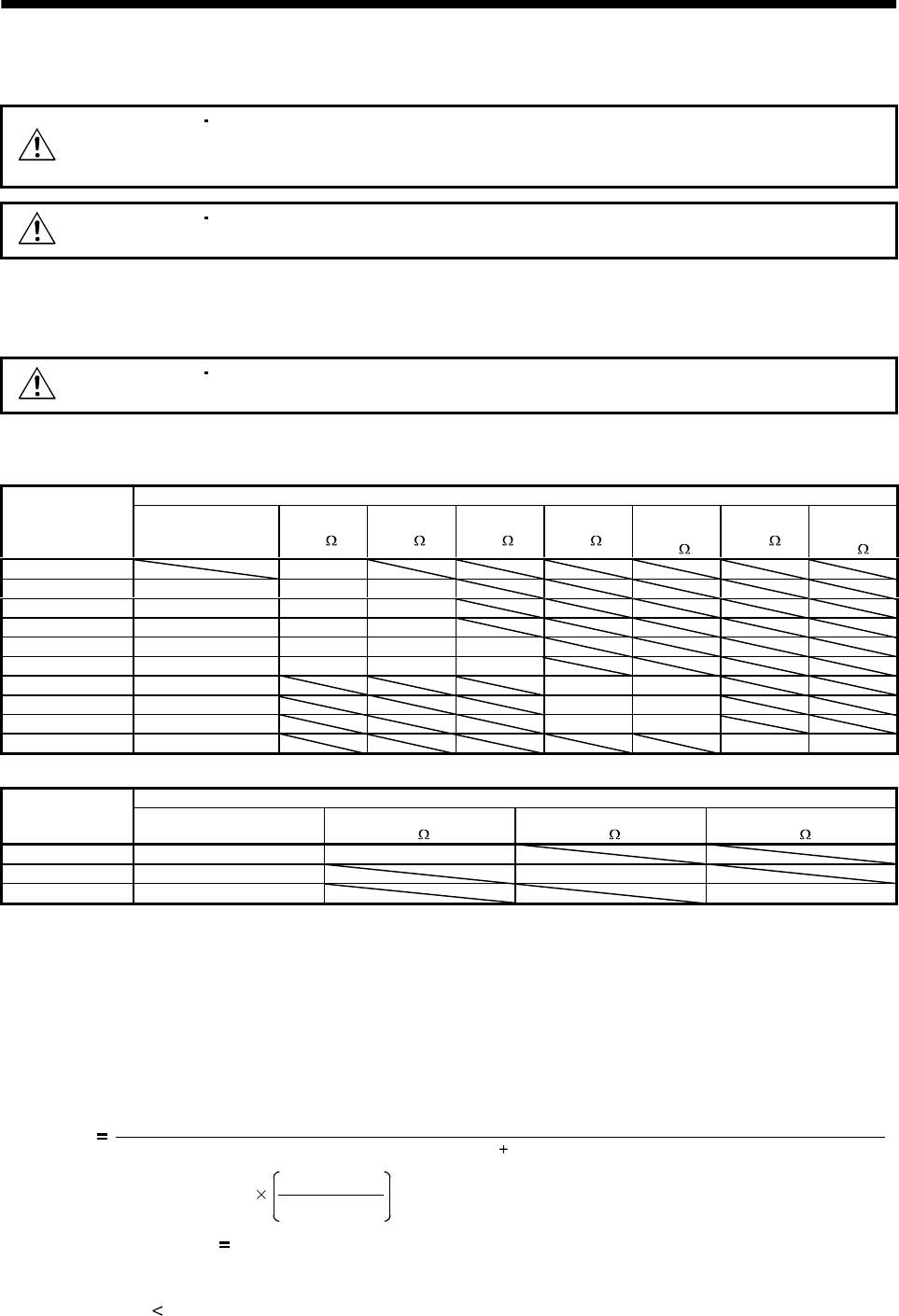
(1) Combination and regenerative power
The power values in the table are resistor-generated powers and not rated powers.
Regenerative power[W]
Servo amplifier
Built-in regenerative
brake resistor
MR-RB032
[40
]
MR-RB12
[40 ]
MR-RB32
[40 ]
MR-RB30
[13 ]
(Note)
MR-RB50
[13
]
MR-RB31
[6.7
]
(Note)
MR-RB51
[6.7
]
MR-J2S-10A(1) 30
MR-J2S-20A(1) 10 30 100
MR-J2S-40A(1) 10 30 100
MR-J2S-60A 10 30 100
MR-J2S-70A 20 30 100 300
MR-J2S-100A 20 30 100 300
MR-J2S-200A 100 300 500
MR-J2S-350A 100 300 500
MR-J2S-500A 130 300 500
MR-J2S-700A 170 300 500
Note. Always install a cooling fan.
(Note) Regenerative power[W]
Servo amplifier
External regenerative
brake resistor (Accessory)
MR-RB65
[8
]
MR-RB66
[5 ]
MR-RB67
[4 ]
MR-J2S-11KA 500 (800) 500 (800)
MR-J2S-15KA 850 (1300) 850 (1300)
MR-J2S-22KA 850 (1300) 850 (1300)
Note. Values in parentheses assume the installation of a cooling fan.
(2) Selection of the regenerative brake option
(a) Simple selection method
In horizontal motion applications, select the regenerative brake option as described below:
When the servo motor is run without load in the regenerative mode from the running speed to a
stop, the permissible duty is as indicated in Section 5.1 of the separately available Servo Motor
Instruction Manual.
For the servo motor with a load, the permissible duty changes according to the inertia moment of
the load and can be calculated by the following formula:
Permissible
duty
Permissible duty for servo motor with no load (value indication Section 5.1 in Servo Motor Instruction Manual)
(m 1)
ratedspeed
running speed
[times/min]
2
where m
load inertia moment/servo motor inertia moment
From the permissible duty, find whether the regenerative brake option is required or not.
Permissible duty
number of positioning times [times/min]
Select the regenerative brake option out of the combinations in (1) in this section.